background image


Right choice for ultimate yield 

LSIS strives to maximize customers' profit in gratitude of choosing us for your 

partner. 


SV-iE5 User Manual 


0.1~0.4kW (200V)


z


Read this manual carefully before

installing, wiring, operating, servicing

or inspecting this equipment.   


z


Keep this manual within easy reach

for quick reference. 

Summary of Contents for SV-iE5 Series

Page 1: ...e customers profit in gratitude of choosing us for your partner SV iE5 User Manual 0 1 0 4kW 200V z Read this manual carefully before installing wiring operating servicing or inspecting this equipment zKeep this manual within easy reach for quick reference ...

Page 2: ...pacitor exposure zDo not remove the cover except for periodic inspections or wiring even if the input power is not applied Or it may cause an electric shock due to charged capacitor exposure even if the power is cut off zWiring and periodic inspections should be performed at least 10 minutes after disconnecting the input power and after checking the DC link voltage is discharged with a meter below...

Page 3: ... to the specified weight zDo not stack the inverter boxes higher than recommended zInstall according to instruction specified in this manual zDo not open the cover during transport zDo not place any heavy load on the inverter zCheck whether the inverter mounting direction is correct zDo not drop the inverter or subject it to impact zFollow your national electrical code for grounding 200V zAs soon ...

Page 4: ...atically occur Check that the reference signal is turned off in advance Otherwise an accident could occur zDo not modify or alter the inverter without permission zDo not use a magnetic contactor on the inverter input for frequent starting stopping of the inverter zUse a noise filter to reduce the effect of electromagnetic interference Otherwise nearby electronic equipment may be affected zIn case ...

Page 5: ...al instructions zMany of the diagrams and drawings in this instruction manual show the inverter without a circuit breaker a cover or partially open Never run the inverter like this Always place the cover with circuit breakers and follow this instruction manual when operating the inverter ...

Page 6: ...vices to the inverter 5 Loader Illustrates keypad features and display 6 Basic Operation Provides instructions for quick start of the inverter 7 Function List Summarized table of functions 8 Control Block Diagram Shows control flow to help users easily understand operation mode 9 Basic Functions Provides information on basic functions such as frequency setup and operation commands 10 Advanced Func...

Page 7: ... Magnetic Contactor 4 2 4 3 Recommended Reactors 4 2 5 Loader 5 1 5 1 Configuration 5 1 5 2 Alpha numeric view on the LED 5 2 5 3 Moving to other groups 5 3 5 4 How to move among codes in a group 5 4 5 5 How to set parameters 5 7 5 6 Monitoring Operation Status 5 9 6 Basic Operation 6 1 6 1 Frequency Setting and Basic Operation 6 1 7 Function List 7 1 8 Control Block Diagram 8 15 8 1 Control Flow ...

Page 8: ...g 11 1 11 1 Operating Status Monitoring 11 1 11 2 Monitoring I O Terminal 11 3 11 3 Monitoring Fault Condition 11 3 11 4 Analogue output 11 5 11 5 Multi function output terminal and Relay 11 6 12 Protective Function 12 1 12 1 Overload Trip 12 1 12 2 Stall prevention 12 1 12 3 User s fault detection 12 2 12 4 External trip signal 12 3 12 5 Frequency command loss 12 4 12 6 Inverter overload 12 5 13 ...

Page 9: ...4 5 Operation 14 4 14 6 COM Protocol ModBus RTU 14 4 14 7 Communication Protocol LS BUS 14 5 14 8 Parameter code list 14 9 14 9 Troubleshooting 14 15 14 10 ASCII Code List 14 16 15 Specifications 15 1 15 1 Technical data 15 1 DECLARATION OF CONFORMITY 15 1 ...

Page 10: ...c contact your dealer or sales representative refer to the rear cover page of this manual Preparations of instruments and parts required for operation Instruments and parts to be prepared depend on how the inverter is operated Prepare optional additional equipments and parts as necessary Installation To operate the inverter with high performance for a long time install the inverter considering a p...

Page 11: ...wiring and installing Status LED display Inverter nameplate Indicating the capacity and rating of the inverter Variable resistance for frequency setting RUN button Cover screws Power input NPN PNP Select switch COM part built in for COM type product Inverter ground terminal Versatile relay output terminal Control signal terminal Motor output lower DC power upper Analogue input select switch ...

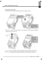
Page 12: ...it up and removing the fixed part Wiring and installation is available only with the cover removed Caution For the control terminal use the cables presented in this manual Using a thicker one than the reference type may interfere with assembling or subject the cable sheath to damage Press the indented sides to remove the cover Remove the screw for wiring After the cover removed the terminal wiring...

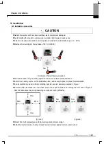
Page 13: ... operation Install it on a flame retardant surface zInverter is a heating source so the installation place needs enough space for proper heat dissipation zIn case installed in a panel without ventilating opening secure space as presented in Figure 1 zIf the inverters are installed in a row make sure to leave space between and among them as seen in Figure 2 Note that side space may vary depending o...

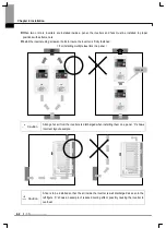
Page 14: ...sure the inverter is firmly fastened For installing multiple inverters in a panel Caution Arrange hot air from the inverters is discharged when installing them on a panel X shows incorrect layout example Caution A fan is to be installed so that the air inside the inverter is well discharged as seen in the left figure X shows an example of reduced cooling effect possibly causing the inverter to ove...

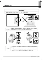
Page 15: ...l the inverter vertically possible to air circulation Malfunction or fire may be caused when installed horizontally Caution z Heat protection pin of iE5 is a high heating element Caution to contact while operate the products z Since switching heat occurs when inverter output without connection motors Do not operate inverter independently Skin burn or malfunction may be caused ...

Page 16: ... 1 001iE5 2 002iE5 2 004iE5 2 W 68 68 68 68 68 68 H 128 128 128 128 128 128 D 85 85 115 85 85 115 H1 124 124 124 124 124 124 W1 64 64 64 64 64 64 φ 4 2 4 2 4 2 4 2 4 2 4 2 Weight kg 0 44 0 46 0 68 0 43 0 45 0 67 Note Use M4 screw for fixing the inverter on a panel W H D H1 W1 ...

Page 17: ...2 O wire thickness 16AWG 1 25 mm2 G wire thickness 14AWG 1 25 mm2 I O terminal 16AWG 1 25 mm2 3 5 φ Terminal torque 3 5 lb in 220Vac U V W P P1 DCN R S T 30A 30B 30C A contact output B contact output A B contact common Multi function relay output terminal Multi function Input terminal Input signal common 12V power 12V 100mA for external volume Default FX forward run RX reverse run EST emergency st...

Page 18: ... inside the inverter it can cause faults breakdowns and malfunctions zNever short P1 or P with N Shorting terminals may cause internal inverter damage zDo not connect static condenser surge killer or radio noise filter to the output of the inverter Otherwise the inverter s protection function starts working or it may cause condenser or surge suppressor broken zThe inverter is delivered that P P1 a...

Page 19: ...ommon terminal 22 AWG 0 3 mm2 3 0 Multi function Relay T M Spec 30A 30B 30C T M Terminal description Wire size Torque lb in Remarks 30A Multi function relay output A contact 20 AWG 0 5 mm2 4 5 30B Multi function relay output B contact 20 AWG 0 5 mm2 4 5 30C Common for Multi function relays 20 AWG 0 5 mm2 4 5 CAUTION Tie the control wires more than 15cm away from the control terminals Otherwise it ...

Page 20: ...l 24V Voltage input V right Analogue voltage input Current input I left Analogue current input Note The setting direction of switch in the above figure is in black P1 P2 P3 P4 P5 CM P1 P2 P3 P4 P5 CM z24 Vdc 0 20mA AI CM 0 10Vdc 1 10kΩ AI CM VR AI CM 2 Using external voltage 3 Using variable resistor 1 Using external current ...

Page 21: ... inrush current may flow in the inverter at power on Magnetic contactor Install it if necessary When installed do not use it for the purpose of starting or stopping Otherwise it may cause the reduction of product life AC or DC reactors The reactors must be used when the power factor is to be improved or the inverter is installed near a large power supply system 20times and more than its cap and wi...

Page 22: ...15A 15A GMC 18 13A 001iE5 2 3A 3A GMC 9 7A 002iE5 2 5A 5A GMC 9 7A 004iE5 2 ABS33b 10A EBS33b 10A GMC 12 9A 4 3 Recommended Reactors Model AC Input fuse AC reactor DC reactor 001iE5 1 20A 4 2mH 3 5A 10mH 3A 002iE5 1 20A 4 2mH 3 5A 10mH 3A 004iE5 1 20A 5 1mH 5 4A 7mH 5A 001iE5 2 20A 4 2mH 3 5A 10mH 3A 002iE5 2 20A 4 2mH 3 5A 10mH 3A 004iE5 2 20A 4 2mH 3 5A 7mH 5A ...

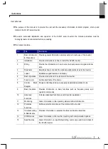
Page 23: ...splaying operation status and parameter information Key Name Description S Up Scroll through codes or increase parameter value T Down Scroll through codes or decrease parameter value RUN Run Operation command STOP Stop STOP stop during operation RST reset in case of fault FUNC Function Edit parameters or save edited parameter values SHFT Shift Move among groups the number of ciphers left during pa...

Page 24: ... the above table Make sure to fully comprehend them for reading the fault messages functional information Note The 7 Segment operates in three statuses on off and blink Throughout this manual on is in black blank is in grey and off is not separately presented i e Inverter LED No Inverter LED Eng Inverter LED Eng Inverter LED Eng 0 A K U 1 B L V 2 C M W 3 D N X 4 E O Y 5 F P Z 6 G Q 7 H R 8 I S 9 J...

Page 25: ...n other codes but 0 it moves to the first code of a selected group and it moves between groups if pressing SHFT once more 1 Target frequency is set in the first code of Drive Group It is delivered with 0 00 set as the default and any differently changed driving frequency is displayed once a user changes it Type Description Drive group Basic parameters necessary to operate the inverter target frequ...

Page 26: ... code of Drive Group zCode change in Drive Group 1 It displays 0 00 the 1st code of Drive Group Press UP S key 2 It displays ACC the 2nd code of Drive Group Press UP S key 3 It displays dEC the 3rd code of Drive Group Keep pressing UP S key 4 It displays drC the final code of Drive Group Press UP S key in the final code of Drive Group 5 It returns to the 1st code of Drive Group Note Drive group Fo...

Page 27: ...e 15 is possible Pressing FUNC key enters 15 F U N C S H F T X5 F U N C 5 SET lamp is out It displays Code 15 of PG Group zCode change in PG Group Moving from code 1 to code 15 in PG group 1 It displays Code 1 of PG Group Keep pressing UP S key until P 15 is displayed 2 It displays Code 15 of PG Group Note Some codes will be skipped in the middle of increment S decrement T for code change in PG Gr...

Page 28: ...ey until 5 is displayed 3 The second decimal is changed to 5 Press SHFT key 4 The first decimal 0 becomes active Press SHFT key twice 5 The first digit 0 becomes active Set 3 using UP S key 6 Press FUNC key 7 30 05 blinks quickly and it asks whether to save the value Press FUNC key 8 SET lamp is out Blink stops and the saved target frequency are displayed Note Parameter setting is disabled when pr...

Page 29: ...s moved to the first digit Press UP S key 5 The digit to change is increased being changed to 6 0 Press Shift SHFT key 6 The digit to change is moved the tenth digit Press UP S key 7 It displays 16 0 Press Function FUNC key 16 0 blinks wholly 1 Press Function FUNC key ACC duration of 16 0 seconds is entered 8 SET lamp is out It displays ACC ACC duration is changed to 16 0 seconds 1 That every digi...

Page 30: ...y using UP S key 3 The first digit is changed to 4 Press SHFT key 4 0 in 04 is active Increase up to 3 by using UP S key 5 Can move to Code 34 Press FUNC key 6 SET lamp is out It means the current position is Code 34 of PG Group Press FUNC key 7 SET lamp light up Code 34 is set to 0 Increase it to 1 by using UP S key 8 Press FUNC key Press FUNC key once more when 1 blinks SET lamp is out 9 Functio...

Page 31: ... of Drive Group is displayed Press UP S key or DOWN T key until Cur is displayed 2 Moved to a code to monitor output current Press FUNC key 3 Present output current is 2 5 A Press FUNC key 4 Return to the output current monitoring code Note Other parameters in Drive group such as dCL Inverter DC link voltage or vOL Inverter output voltage can be monitored via the same method ...

Page 32: ...S key or DOWN T key 2 The run frequency at the time of trip is displayed Press UP S key 3 The output current at the time of trip is displayed Press UP S key 4 Operating status is displayed A fault occurred during acceleration Press STOP key 5 A fault condition is cleared and nOn is displayed Note Trip occurrence is displayed in one of modes like ACC DEC Stp or Std Fault causes may be expected by u...

Page 33: ...ning it off fault info is moved to fault history P 1 of PG Group However if any the existing fault history moves from P 1 to P 2 or from P 2 to P 3 the latest fault info is saved in P 1 through P 3 When Overcurrent OCt overvoltage Ovt and overheat OHt occur simultaneously When various trips occur simultaneously it shows like the figure above and it can show up to 3 trips Overcurrent Overvoltage Ov...

Page 34: ...links Press SHFT three times 3 00 00 is displayed and the very left 0 blinks Press UP S key 4 Confirming 10 00 press FUNC key 10 00 blinks quickly as a whole Press FUNC key once more 5 Target frequency is changed to 10 00Hz Turn on the switch between P1 FX and CM terminals 6 FWD forward run lamp of the inverter display blinks and accelerating frequency is displayed on the LED When target run frequ...

Page 35: ...equency setting mode is changed to loader volume Press SHFT moves to target frequency the first code of Drive Group Turn the loader volume to MAX or MIN to set to 10 00Hz 6 Turn on the switch between P1 FX and CM FWD forward run lamp of the inverter display blinks and accelerating frequency is displayed on the LED When run frequency 10Hz is reached the value is displayed as shown left Turn off the...

Page 36: ...tting mode is changed to 0 keypad of the loader Press UP S key two times 8 Frequency setting mode may be changed to 3 loader s volume resistance Press FUNC key twice 9 It displays Frq and frequency setting mode is changed to loader volume Turn the loader volume to set to 10 00 in either Max or Min direction 10 Press RUN key FWD forward run lamp of the inverter display blinks and accelerating frequ...

Page 37: ...peration this parameter serves as acc dec time 0 10 0 O 9 8 0 Operate with RUN STOP key of the loader 9 5 1 FX forward run RX reverse run 2 Terminal operation FX Run stop command RX Reverse rotation 9 6 drv Drive mode 0 3 3 communication communication option 1 X 0 Set loader digital frequency 1 9 1 1 Digital Set loader digital frequency 2 9 1 2 Terminal AI input 9 3 3 Loader volume resistance 9 2 ...

Page 38: ...rotation RPM 11 1 dCL Inverter DC voltage Display DC voltage inside the inverter 11 1 vOL Output voltage Display the inverter s output voltage vOL 11 2 nOn Fault display Display the types of fault frequency current and operation status 11 4 If operation command mode drv is set to 0 select the direction of motor rotation F Forward operation drC Selection of motor rotation direction F r r Reverse op...

Page 39: ...rotation 0 2 2 Reverse rotation prohibited 0 X 9 7 P 6 Acc pattern 0 Linear pattern operation P 7 Dec pattern 0 1 1 S curve pattern operation 0 X 9 9 0 Deceleration to stop 1 DC brake to stop P 8 Stop mode selection 0 2 2 Free run to stop 0 X 9 14 P 9 1 DC brake start frequency 0 1 60 Hz It sets DC brake start frequency It cannot be set below start frequency P18 5 00 X P10 DC brake wait time 0 60 ...

Page 40: ...uency 40 200 Hz If changing the max frequency all other frequency parameters but P17 base frequency would be changed to the frequency if they are above the new max frequency 60 00 X 9 8 P17 Base frequency 30 200 Hz The inverter outputs its rated voltage to the motor at this frequency 60 00 X P18 Start frequency 0 1 10 Hz The inverter starts to output its voltage at this frequency It is lower frequ...

Page 41: ...urns off the inverter output when overload trip level current P25 flows for overload trip time 60 0 12 1 Sets stall prevention function Func Set During dec During constant run During acc bit 2 bit 1 bit 0 0 1 3 2 3 3 3 3 4 3 5 3 3 6 3 3 P27 Stall prevention select 0 7 7 3 3 3 0 X 12 1 P28 Stall prevention level 30 150 It sets the amount of current to activate stall prevention function based on the...

Page 42: ...ult detection items at operator s discretion Func Set Earth detection during run GCt Input phase detection CoL Output phase detection Pot bit2 bit1 bit0 0 1 3 2 3 3 3 3 4 3 5 3 3 6 3 3 P33 Operator s fault detection 0 7 bit 7 3 3 3 0 O 12 2 P34 Power On Start Selection 0 1 It is activated when drv is set to 1 or 2 Motor starts acceleration after AC power is applied while FX or RX terminal is ON 0 ...

Page 43: ...ng motor Func Set Power on start P34 Restart after instant power failure Operation on after fault P35 Normal acc bit3 bit2 bit1 bit0 0 1 3 2 3 3 3 3 4 3 5 3 3 6 3 3 7 3 3 3 8 3 9 3 3 10 3 3 11 3 3 3 12 3 3 13 3 3 3 14 3 3 3 P36 Speed search selection 0 15 bit 15 3 3 3 3 0 X P37 Speed Search Current Level Limits the amount of current during speed search operation based on motor rated current P43 10...

Page 44: ...frequency and the value calculated by converting rpm described in the nameplate to frequency 3 X P43 Motor rated current 0 0 25 5 A Enter motor rated current on the nameplate X P44 No Load Motor Current 0 0 25 5 A Enter the current value detected when the motor is rotating in rated rpm after the load connected to the motor shaft is removed Enter the 50 of the rated current value when it is difficu...

Page 45: ...00 O P52 Lower limit of PI frequency 0 1 200 Hz It limits the amount of the output frequency through the PI operation It is settable within the range of Max frequency P16 and Start frequency P18 0 50 O 10 8 It selects the parameter to be displayed first on the display of inverter when the power is applied 0 Operation frequency 1 Acc time 2 Dec time 3 Drive mode 4 Frequency mode 5 Multi step freque...

Page 46: ...nalogue input as the percentage of the whole input 100 O P59 Frequency corresponding to AI max input 0 200 Hz Frequency in case analogue input is the max value 60 00 O 9 3 P60 Filter time constant for Volume input 0 9999 Adjusts the responsiveness of volume input operation 10 O P61 Min value for volume input 0 100 Sets the min rpm of volume input as the percentage of the whole input 0 O P62 Freque...

Page 47: ... 4 Jog operation command JOG 2 O 10 3 5 Multi Step freq low P69 Multi function input terminal P4 define 6 Multi Step freq high 3 O 9 5 7 8 9 10 11 DC brake during stop 10 1 12 13 14 15 Frequency up 16 Up down Frequency down 10 4 17 3 wire operation 10 4 18 External trip A Contact EtA 19 External trip B Contact EtB 12 5 20 Change from PI operation to general operation 21 22 Analog Hold 9 4 23 Accel...

Page 48: ...oltage DC 400V 0 O 11 5 P74 Analog output level adjustment 10 200 Based on 10V 100 O P75 Frequency detection level 30 00 O P76 Frequency detection bandwidth 0 200 Hz Used when P77 is set to 0 4 Cannot be set higher than P16 10 00 O 11 7 11 9 0 FDT 1 1 FDT 2 11 7 2 FDT 3 3 FDT 4 11 8 4 FDT 5 5 6 Inverter Overload IOLt 7 Motor stall STALL 8 Over voltage trip OVt 9 Low voltage trip LVt 10 Inverter co...

Page 49: ... 485 0 2400 bps 1 4800 bps P80 Baud rate 0 2 2 9600 bps 2 O 14 3 It is used when freq command is given via Analog signal volume AI or RS 485 0 Continuous operation at the frequency before its command is lost 1 Free Run stop Output cut off P81 Drive mode select after loss of frequency command 0 2 2 Decel to stop 0 O 12 4 P82 Wait time after loss of frequency command 0 1 120 sec Time inverter determ...

Page 50: ...both groups 2 Initialize Drive Group P85 Parameter initialization 0 3 3 Initialize PG Group 0 X 10 13 P86 Password registration 0 FFFF Enter password to prohibit parameter change Set it as hexadecimal number 0 O 10 14 Prohibit or cancel parameter change prohibition by using the password set in P86 UL Unlock Enable parameter change P87 parameter change prohibition 0 FFFF L Lock Disable parameter ch...

Page 51: ...ale PG group P55 P60 PG group P56 P64 PG group P72 P1 P2 P3 P4 P5 PG group P16 P18 Max Min frequency Step frequency setting PG group P66 P70 PG group P66 P70 0 1 PG group P66 P70 3 Wire operation 17 Drive group drv Operation command setting 0 1 2 PG group P 5 FX RX operation disable Forward run disable Reverse run disable 1 2 FX RX run enable 0 Jog frequency Frq setting PG group P66 P70 Up down op...

Page 52: ... Output voltage adjustment PG group P17 P18 Base start frequency PWM PG group P31 Dwell operation P32 Dwell freq time PG group P 8 Stop method select 0 1 2 DC brake Free run stop PG group P9 P12 DC brake freq Voltage time PG group P9 P12 DC brake start frq Operation command DC brake voltage time Frequency setting Operation Stop Drive group ACC DEC Accel decel time PG group P16 Max frequency PG gro...

Page 53: ... 00 Frequency command 0 200 0 0 Hz Drive Group Frq Frequency mode 1 0 4 0 Set Frq Frequency mode to 1 In 0 00 frequency is changed upon pressing the Up S Down T key In this case UP Down keys serve as volume resistance The value is settable less than the max frequency P16 zUsing Loader s volume resistance run in case of Frq 3 SV iE5 series basically offer volume resistance on the inverter s loader ...

Page 54: ...in Frq code of Drive group It is possible to monitor frequency setting in Command Frequency Code 0 0 of Drive Group P60 Filter time constant for V0 input Effective for eliminating noise in the frequency setting circuit Increase the filter time constant if steady operation cannot be performed due to noise A larger setting results in slower response t gets longer P61 P64 Setting input range and corr...

Page 55: ...ng 0 10V in an external control or connecting variable resistance to VR AI CM terminals of the inverter Inverter terminal may be wired as follows and see page 9 2 for the functions of P55 through P59 Depending on AI selection switch beside the inverter s control terminal as V I it is possible to select one of voltage input and current input Caution For AI selection set it accurately according to t...

Page 56: ...ration command Setting frequency 9 2 Multi Step Frequency Setting Group Code Parameter Name Setting Range Initial Unit 0 0 Frequency command 5 0 0 200 0 0 Hz Frq Frequency setting mode 0 0 4 0 St1 Multi step freq 1 10 0 St2 Multi step freq 2 20 0 Drive Group St3 Multi step freq 3 0 200 30 0 Hz P68 Multi function input terminal P3 define 5 2 PG Group P69 Multi function input terminal P4 define 6 0 ...

Page 57: ... rotation direction select F r F Set drive code of Drive Group to 0 Acceleration is started upon pressing the Run key while operating frequency is set Motor decelerates to stop by pressing the STOP RST key Selecting rotation direction is available at drC Direction of motor rotation select when operating command is set to 0 F Forward drC Direction of motor rotation select r Reverse Spee d FX RX P4 ...

Page 58: ... Motor is stopped when FX RX terminal is ON OFF at the same time FX RX Frequency Time zOperating command via FX RX terminal 2 Group Code Parameter Name Setting Range Initial Unit Drive Group drv Drive mode 2 0 3 1 P66 Multi function input terminal P1 define 0 0 24 0 PG Group P67 Multi function input terminal P2 define 1 0 24 1 Set drv code of Drive Group to 2 Set P66 and P67 to 0 and 1 to use P1 a...

Page 59: ...le zPower On Start select Group Code Parameter Name Setting Range Initial Unit Drive Group drv Drive mode 1 2 0 3 1 PG Group P34 Power on start select 1 0 1 0 Set P34 to 1 When AC input power is applied to the inverter with drv set to ON motor starts acceleration It is inactive when it is operated by RUN key Caution Particular attention must be directed to this function due to potential hazard as ...

Page 60: ...r the fault is cleared Operation command Reset Frequency P35 0 P35 1 Time Time 9 4 Accel Decel time and pattern setting zAccel Decel time setting based on Max frequency Group Code Parameter Name Setting Range Initial Unit ACC Accel time 0 6000 5 0 Sec Drive Group dEC Decel time 0 6000 10 0 Sec PG Group P16 Max freq 0 200 60 0 Hz Set the desired Accel Decel time at ACC dEC code in Drive group Accel...

Page 61: ...attern run PG Group P 7 Decel pattern 1 S shape pattern run 0 Accel decel patterns may be set in P6 and P7 codes of PG Group respectively Linear pattern operation Output frequency linearly increases or decreases at uniform incremental S shape pattern run Used for applications needing smoothing acceleration deceleration such as conveyor or elevator door Note In case of S shape pattern runs the acce...

Page 62: ...Target frequency Max frequency Time zAccel Decel Disable Group Code Parameter Name Setting Range Initial Unit P66 Multi function input terminal P1 define 0 PG Group P70 Multi function input terminal P5 define 23 0 24 4 Select one terminal among Multi function input terminals P1 P5 to define Accel Decel disable If P5 is selected set P70 to 23 to activate this function Frequency P5 Operation command...

Page 63: ... Group P22 V F pattern 0 0 1 0 Set P22 code to 0 linear This pattern maintains a linear volts frequency ratio by voltage frequency V F Base frequency Inverter outputs its rated voltage at this level Enter the motor nameplate frequency Start frequency Inverter starts to output its voltage at this level Operation command Frequency Start frequency Base frequency Voltage Inverter rated voltage Time Ti...

Page 64: ... the Squared V F pattern to secure operation torque it is practically realized with approximate value to 1 4 squared zOutput voltage adjustment Group Code Parameter Name Setting Range Initial Unit PG Group P23 Output voltage adjustment 40 110 100 This function is used to adjust the output voltage of the inverter This is useful when you use a motor that has a rated voltage lower than the input volt...

Page 65: ...set separately in P20 and P21 Caution If the boost value is set much higher than required it may cause motor overheating due to over energizing FX Time RX Voltage FX torque boost Without torque boost 100 RX torque boost zAuto torque boost Group Code Parameter Name Setting Range Initial Unit PG Group P19 Torque boost select 1 0 1 0 PG Group P44 No load motor current 0 1 25 5 A Set P19 code of PG Gr...

Page 66: ...uency Decel time Time zDC braking to stop Group Code Parameter Name Setting Range Initial Unit PG Group P 8 Stop mode select 1 0 2 0 Select 1 DC brake to stop in P8 code of PG Group Refer to page 10 1 zFree run stop Group Code Parameter Name Setting Range Initial Unit PG Group P 8 Stop mode select 2 0 2 0 Select 2 Free run stop in P8 code of PG Group When operating command is turned OFF Output Fre...

Page 67: ... frequency has upper limit of frequency parameter Therefore any frequency cannot be set above the max frequency Start Frequency Every frequency has lower limit of frequency parameter If a frequency is set lower than this 0 00 is automatically set Max frequency is the reference frequency serving as the criteria of accel decel time as well as upper limit Once max frequency is changed accel decel slo...

Page 68: ...10 Inverter output will hold for this time before applying DC brake voltage P11 Set this value as a percent of Motor rated current P12 Sets the time for DC brake voltage to be applied to the motor Caution If excessive DC Brake voltage is set or DC Brake time is set too long it may cause motor overheating and damage to the motor Setting P11 or P12 to 0 will disable DC brake DC Brake Wait time When ...

Page 69: ...to 0 will disable Starting DC brake t After P14 the frequency starts accelerating zDC brake at a stop Group Code Parameter Name Setting Range Initial Unit PG Group P13 DC brake start voltage 0 200 50 PG Group P68 Multi function input terminal P3 function select 11 0 24 2 P13 It sets the level as a percent of Motor rated current Select a terminal to issue a command of DC brake at a stop among P1 to...

Page 70: ... P5 to use for this setting If P3 is set for Jog operation set P68 to 4 Jog operation Jog frequency can be set within Max frequency P16 and Start frequency P18 Jog operation overrides all other operations except Dwell operation Therefore if Jog frequency command is entered in the middle of Multi Step Up Down or 3 wire operation operation is executed at Jog frequency The above diagram shows an exam...

Page 71: ...n Save function If P29 Save up down frequency is set to 1 the frequency before the inverter was stopped or decelerated is saved in P30 0 Remove save up down frequency P29 Save up down frequency select 1 Set save up down frequency P30 Save up down frequency Up down frequency saved The Up down frequency can be initialized by setting of the multi function input terminal as Up Down Save Frequency Init...

Page 72: ...n 50msec 10 5 Dwell operation Group Code Parameter Name Setting Range Initial Unit P31 Dwell frequency 0 200 5 0 Hz PG Group P32 Dwell time 0 10 0 0 sec In this setting a motor begins to accelerate after dwell operation is executed for dwell time at the specified dwell frequency It is mainly used to release mechanical brake in elevators after operating at dwell frequency Dwell frequency This funct...

Page 73: ...rol Group Code Parameter Name Setting Range Initial Unit P40 Motor type select 0 1 0 4 P41 No of motor poles 2 12 4 P42 Rated slip frequency 0 10 Hz P43 Motor rated current 0 0 25 5 A P44 Motor no load current 0 0 25 5 A PG Group P46 Control mode select 1 0 2 0 Set P46 to 1 Slip compensation control This function enables the motor to run in constant speed by compensating inherent slip in an induct...

Page 74: ... 0 1 0 6 0 4 2 0 0 2 1 1 0 7 2 33 0 4 1 8 1 2 3 00 P43 Enter the motor nameplate rated current P44 Enter the measured current when the motor is running at rated frequency after the load is removed Enter 50 of the rated motor current when it is difficult to measure the motor no load current Induction motor has a large difference between motor rated rpm and frequency synchronous speed depending on l...

Page 75: ...se as constant control of flow pressure or temperature P47 Set the percentage of output to error If P Gain is set to 50 50 of the error value will be output Higher value can reach the target control value faster but it may cause oscillation P48 Set the time to output the accumulated error value Set the time required to output 100 when the error value is 100 If differential time is set to 1 second ...

Page 76: ...put filter PG group P56 P64 Analog input scale 1 2 3 Loader key setting 1 0 I V1 Loader volume Loader key PG group P46 Control mode select 2 P1 P5 Accel Decel PG group Analog input filter Analog input scale AI PG group P48 I time PG group P50 Feed forward gain PG group P66 P70 Switching from PI operation to normal operation PG group P51 PI output freq limit 0 1 0 1 2 3 P55 P55 P60 P56 P64 Comm inp...

Page 77: ...ut current Therefore detecting exact speed is difficult zThe following table shows 4 types of Speed search selection Speed search during P34 power on start Speed search during instant power failure restart Speed search during P35 restart after fault reset Speed search during acceleration Set bit 3 bit 2 bit 1 bit 0 0 1 9 2 9 3 9 9 4 9 5 9 9 6 9 9 7 9 9 9 8 9 9 9 9 10 9 9 11 9 9 9 12 9 9 13 9 9 9 1...

Page 78: ...frequency before trip Speed search operation is suitable for loads with high inertia Stop the motor and restart when friction in the load is high SV iE5 series keeps normal operation when power is restored in 15msec for the use of its inverter rating if it operates within the rated output 0 1kW 0 2kW and 0 4kW inverter types Inverter DC link voltage can vary depending on output load quantity There...

Page 79: ...reset restart try auto restart function is deactivated If the setting is reset via the control terminal or the STOP key on the loader the number of auto restart try set by user is automatically entered If there is no more trip for 30 sec after Auto restart operation it increases the preset auto restart value reduced in the inverter When operation is stopped due to Low voltage Lvt or Emergency stop...

Page 80: ...ries are designed to monitor the temperature of the inverter s cooling coil heat sink in order to automatically adjust carrier frequency in overheating condition If it is necessary to use high carrier select inverter type considering ambient temperature and motor load 10 11 Parameter initialize Lock zParameter initialize Group Code Parameter Name Setting Range P85 Parameter initialize 0 0 1 Groups...

Page 81: ...the registered password If forgetting the password you need to get after sales service Follow the steps to register password If password is already set it is necessary to enter the present password instead of 0000 in step 2 No Display Description 1 Move to P86 Pressing FUNC key shows 0000 2 Enter the present password and press FUNC key The factory default password is 0000 Press FUNC key 3 Register...

Page 82: ...UNC key shows UL unlock 2 Display whether or not function code is changeable UL unlock shows that function code is changeable Press FUNC key 3 Indicating 0000 the present password entry window is displayed Enter the present password i e A123 4 Press FUNC key 5 If password is correct it is changed to L lock if incorrect it shows UL unlock again Function code is locked Press FUNC key 6 Initial menu ...

Page 83: ...rol or 1 PID control the Inverter output frequency f is displayed in RPM using the formula below without Motor slip considered P41 Enter the number of rated motor poles on the nameplate P54 Enter gear ratio to monitor mechanical rotation instead of rotation of motor axis zInverter DC link voltage Group Code Parameter Name Setting Range Initial Unit Drive Group dCL Inverter DC link voltage Inverter...

Page 84: ... Accel time ACC 2 Decel time DEC 3 Drive mode drv 4 Frequency mode Frq 5 Multi step frequency 1 6 Multi step frequency 2 7 Multi step frequency 3 8 Output current CUr 9 Motor rpm rPM 10 Inverter DC link voltage dCL 11 Output voltage vOL 12 Fault display 1 13 Operating display select 14 Output current PG Group P53 Power on display 15 Motor rpm 0 Display the parameters set in P53 when power on The o...

Page 85: ...tus Group Code Parameter Name Setting Range Initial Unit Drive Group nOn Current fault display Fault occurred during operation is displayed in nOn Up to 3 kinds of faults can be monitored This parameter gives information on fault types and the operating status at the time of the fault in good order of fault type frequency current accel decel Refer to Page 5 10 for keypad setting Frequency Current ...

Page 86: ...ed in the nOn When the fault condition is reset via the STOP RST key or multi function terminal information displayed in the nOn will be moved to P1 In addition the previous fault info stored in P1 will be automatically moved to P2 Therefore the latest update fault info will be stored in the lowest history number When more than 1 fault occurred at the same time up to 3 types of faults will be stor...

Page 87: ...are selectable and adjustable P73 The selected item will be output to Analog output terminal AM Item corresponding to 10V 0 Output frequency Max frequency P16 1 Output current 150 of inverter rated current 2 Output voltage 282Vac P73 Analogue output item select 3 Inverter DC link voltage 400Vdc P74 If you want to use analog output value as a gauge input the value can be adjustable according to var...

Page 88: ...verheat OHt 11 Command loss 12 During run 13 During stop 14 During constant run 15 During speed searching 16 Wait time for run signal input P77 Multi function output terminal select 17 Fault output 17 When setting H26 number of auto restart tries When the other than low voltage trip occurs When the low voltage trip occurs Type Set bit 2 bit 1 bit 0 0 1 9 2 9 3 9 9 4 9 5 9 9 6 9 9 PG Group P78 Faul...

Page 89: ... not be set above max frequency P16 When setting P76 to 10 0 z1 FDT 2 Activated when the preset frequency matches frequency detection level P75 and FDT 1 condition is met Active condition Preset frequency FDT level FDT 1 Group Code Parameter Name Setting Range Initial Unit P75 Detected frequency 30 0 PG Group P76 Detected frequency bandwidth 0 200 10 0 Hz Cannot be set above Max frequency P16 When...

Page 90: ...ting P75 and P76 to 30 0Hz and 10 0 Hz respectively z3 FDT 4 Activated when run frequency meets the following condition Active condition Accel time Run Frequency FDT Level Decel time Run Frequency FDT Level FDT Bandwidth 2 Group Code Parameter Name Setting Range Initial Unit PG Group P75 Detected frequency 30 0 P76 Detected frequency bandwidth 0 200 10 0 Hz Can not be set above max frequency P16 W...

Page 91: ... 10 0 Hz respectively z5 Overload OL Refer to page 12 1 z6 Inverter overload IOL Refer to page 12 5 z7 Motor stall Stall Refer to page 12 1 z8 Over voltage trip Ovt Activated when over voltage trip occurs due to DC link voltage exceeded 400VDC z9 Low voltage trip Lvt Activated when low voltage trip occurs due to DC link voltage under 200V z10 Inverter heatsink overheat OHt Activated when the heats...

Page 92: ...o page 10 10 z16 Wait time for run signal input This function becomes active during normal operation and that the inverter waits for active run command from external sequence z17 Fault output The parameter set in P78 is activated For example if setting P77 P78 to 17 and 2 respectively Multi function output relay will become active when trip other than Low voltage trip occurred Frequency Relay Oper...

Page 93: ... 0 7 3 P28 Stall prevention level 30 150 150 PG Group P77 Multi function relay select 7 0 18 17 During acceleration Motor starts deceleration when current exceeding the value set in P28 flows During constant run Motor decelerates when current exceeding the value set in P28 flows During deceleration Motor deceleration stops when inverter DC link voltage rises above a certain voltage level P28 The v...

Page 94: ...operation 12 3 User s fault detection Group Code Parameter Name Setting Range Initial Unit PG Group P33 User s fault detection 3 0 7 0 Can set the following fault detection Ground fault detection during operation it stops output if excessive current of one or more outputs flows due to ground fault and etc Input phase loss Inverter output is blocked at the event of more than one phase loss among R ...

Page 95: ...input terminal P4 define 18 3 PG Group P70 Multi function input terminal P5 define 19 0 24 4 Select a terminal among P1 P5 to output external trip signal Set P69 and P70 to 18 and 19 to define P4 and P5 as External A contact and B contact External trip signal input A contact N O At normal status P4 and CM terminals are open while at fault inverter output is shut off External trip signal input B co...

Page 96: ...quency command is set to 3 V1 of terminal in Frq code of Drive Group and P65 is set to 1 and when AI is less than half the value set in P56 it determines frequency command loss At the moment if entering current based on the value converting 0 10V to 0 100 it operates with the value converting 0 20mA to 0 100 i e Voltage input If P56 and P65 are set to 50 and 2 respectively it operates at 5V Curren...

Page 97: ...ent above inverter rated current flows At the moment the operation time becomes shorter as larger output current is Multi function relay 30BC is used to output it to external device during inverter overload trip Inverter overload trip operates as follows However level and time may vary automatically in accordance with motor type depending on settings including carrier frequency Frequency Relay Ope...

Page 98: ...rload The inverter turns off its output when the output current of the inverter flows more than the rated level 150 for 1 minute Overload trip The inverter turns off its output if the output current of the inverter more than the motor rated current P25 flows Inverter overheat The inverter turns off its output if the heat sink overheats due to a damaged cooling fan Condenser overload Inverter outpu...

Page 99: ...he inverter The inverter instantly turns off the output when the EST terminal is turned on Note Instant cut off The inverter starts to regular operation when turning off the EST terminal while FX or RX terminal is ON External fault A contact input When multi function input terminal P66 P70 is set to 18 external fault signal input A Normal Open Contact the inverter turns off the output External fau...

Page 100: ...eck output wiring Check the mechanical brake Ground fault current zGround fault has occurred at the output wiring of the inverter zThe insulation of the motor is damaged due to heat Check the wiring of the output terminal Replace the motor Inverter overload Overload trip zLoad is greater than the inverter rating zTorque boost scale is set too large Upgrade the capacity of motor and inverter or red...

Page 101: ...oltage is below its rating Check the incoming AC line Adjust the line capacity corresponding to the load Change a magnetic switch External fault A contact input External fault B contact input zThe multi function terminals P66 P70 set to 18 External fault A or 19 External trip signal input fault B in P66 P70 in PG Group is ON Eliminate the cause of fault at circuit connected to external fault termi...

Page 102: ...Cooling system fault Unusual vibration and noise Unusual overheating and discoloration zPeriodic inspection Do screws and bolts become loose or rust due to the environment Tighten or replace them Alien substances are clogged in the cooling system Eliminate them by using compressed air Check the rotating condition of the cooling fan the condition of capacitors and the connections with the magnetic ...

Page 103: ... form Bus method Multi drop Link System Inverter SV iE5 series Converter RS232 converter Connectable drives Max 16 Transmission distance Max 1 200m within 700m recommended zHardware specification Item Specification Installation Use S S terminals on control terminal block Power supply Use Insulated power from the inverter power supply zCommunication specification Item Specification Communication sp...

Page 104: ...d COM dedicated terminal is delivered with iE5 COM optional product zPC Inverter connection Note The number of drives to be connected is up to 16 drives The specification of length of communication line is max 1200m To ensure stable communication limit the length below 700m Short both S S of JP1 pin located on the upper PBC of control terminal COM terminal Upper controls PC laptop PLC and etc 232 ...

Page 105: ...ithstand voltage DC V 1min Endurable at 500V for 1 minute In the air Insulation resistance MΩ km 1 000 and higher Ambient temp Electrostatic cap Pf M 45 and lower 1kHz Electrical characteristics Characteristic impedance Ω 120 12 10MHz Core Pair 2 Spec AWG 22 Structure NO mm 1 0 643 Conductor Dia Mm 0 643 Thickness mm 0 59 Appearance characteristics insulator Dia Mm 1 94 14 4 Inverter functional co...

Page 106: ...st serves as a master while the inverter servers as a slave The inverter as a slave responds to the read write request of the master zSupportable function codes Function Description Remarks h03 Read Hold Register h04 Read Input Register h06 Preset Single Register h10 Preset Multiple Register z Exception codes Exception Description Remarks h01 ILLEGAL FUNCTION When using other function codes but th...

Page 107: ...bytes 1 byte Description Request starts with ENQ and ends with EOT Acknowledge Response starts with ACK and ends with EOT Negative Acknowledge Response starts with NAK and ends with EOT Drive Number is the number of drives and indicated in 2 bytes ASCII HEX ASCII HEX Hexadecimal consists of 0 9 A F CMD Capital letter Character ASCII HEX Command R 52h Read W 57h Write X 58h Request for monitoring r...

Page 108: ...ol 1 Request for Read Request for read successive N numbers of WORD from address XXXX ENQ Drive No CMD Address Number of address to read SUM EOT 05h 01 1F R XXXX 1 8 n XX 04h 1 byte 2 bytes 1 byte 4 bytes 1 byte 2 bytes 1 byte Total Byte 12 The quotation marks means character 1 1 Acknowledge Response ACK Drive No CMD Data SUM EOT 06h 01 1F R XXXX XX 04h 1 byte 2 bytes 1 byte N 4 bytes 2 bytes 1 by...

Page 109: ... of write and then it send the owned data to the second request of write 2 2 Negative response NAK Drive No CMD Error code SUM EOT 15h 01 1F W XX 04h 1 byte 2 bytes 1 byte 2 bytes 2 bytes 1 byte Total Byte 9 3 Request for Monitor Register This is useful when constant parameter monitoring and data updates are required periodically Request for Register of n numbers of Address not consecutive ENQ Dri...

Page 110: ... Y XXXX XX 04h 1 byte 2 bytes 1 byte n 4 bytes 2 bytes 1 byte Total Byte 7 n 4 Max 23 4 2 Negative response NAK Drive No CMD Error code SUM EOT 15h 01 1F Y XX 04h 1 byte 2 bytes 1 byte 2 bytes 2 bytes 1 byte Total Byte 9 5 Error code Error code Description IF When master is sending codes other than Function code R W X Y IA When parameter address does not exist ID When Data value exceeds its permis...

Page 111: ...ter Lock R W 0 Lock default 1 Unlock h0005 Frequency Command 0 01 Hz R W Starting freq Max freq BIT 0 Stop BIT 1 Forward Run R W BIT 2 Reverse Run BIT 3 Fault Reset RESET W BIT 4 Emergency Stop EST BIT 5 13 15 Not Used BIT 6 7 00 terminal 01 loader 10 Reserved 11 Com operation BIT 8 12 frequency arrival info 00000 DRV 00 00001 multi step 1 00010 multi step 2 00011 multi step 3 00100 UP 00101 Down ...

Page 112: ...unning BIT 3 Fault Trip BIT 4 Accelerating BIT 5 Decelerating BIT 6 speed arrival BIT 7 DC Braking BIT 8 Stopping BIT10 Brake Open BIT11 Forward run command 1 BIT12 Reverse run command 1 BIT13 REM R S h000E Status of Inverter R BIT14 REM Freq BIT 0 OCT BIT 1 OVT BIT 2 EXT A BIT 3 EST Emergency Stop BIT 4 COL BIT 5 GFT Ground Fault BIT 6 OHT Over Heat BIT 7 GCT Ground Current Trip BIT 8 OLT Overloa...

Page 113: ...d or Inverter is reset However changing value is immediately reflected in other parameter groups even in the case of Reset or Power On Off zDRV group Address 16bit 10bit Code Parameter Initial Max Min D100 53504 D00 Cmd Freq 0 Max Freq 0 D101 53505 D01 ACC 50 60000 0 D102 53506 D02 DEC 100 60000 0 D103 53507 D03 DRV 1 3 0 D104 53508 D04 FRQ 0 4 0 D105 53509 D05 ST 1 1000 Max Freq 0 D106 53510 D06 ...

Page 114: ...DcSt value 50 200 0 D20E 53774 P 14 DcSt time 0 600 0 D20F 53775 P 15 Jog Freq 1000 Max Freq 0 D210 53776 P 16 Max Freq 6000 12000 4000 D211 53777 P 17 Base Freq 6000 12000 3000 D212 53778 P 18 Start Freq 50 1000 10 D213 53779 P 19 Trq Boost 0 1 0 D214 53780 P 20 Fwd Boost 50 150 0 D215 53781 P 21 Rev Boost 50 150 0 D216 53782 P 22 VF Pattern 0 1 0 D217 53783 P 23 OV adj 100 110 40 D218 53784 P 24...

Page 115: ...0 10 D232 53810 P 50 PI F gain 0 9999 0 D233 53811 P 51 PI output freq H limit 6000 Max Freq PI output freq L limit D234 53812 P 52 PI output freq L limit 50 PI output freq H limit startFreq D235 53813 P 53 PowerOn disp 0 15 0 D236 53814 P 54 Rpm disp Gain 100 1000 1 D237 53815 P 55 AI input filter cont 10 9999 0 D238 53816 P 56 AI min Input v i 0 AI max inupt 0 D239 53817 P 57 AI min input freq 0...

Page 116: ... 53835 P 75 Det Freq 3000 Max Freq 0 D24C 53836 P 76 Det Freq bandwidth 1000 Max Freq 0 D24D 53837 P 77 Relay func select 17 17 0 D24E 53838 P 78 Fault output select 2 7 0 D24F 53839 P 79 Inv No 1 250 1 D250 53840 P 80 Baud rate 2 2 0 D251 53841 P 81 Lost command 0 2 0 D252 53842 P 82 Determination time of freq input lost 10 1200 1 D253 53843 P 83 COM speed set 5 100 2 D254 53844 P 84 Parity Stop ...

Page 117: ...onverter and computer correct Refer to converter manual Does master start to communicate Start communication Is baud rate of computer and inverter correctly set Set the correct value in accordance with 14 3 Installation 1 Is the data format of user program right Revise User Program Is the connection between converter and communication card right Check for GF the correct wiring in accordance with 1...

Page 118: ... m n o p q r s t u v w x y z 61 62 63 64 65 66 67 68 69 6A 6B 6C 6D 6E 6F 70 71 72 73 74 75 76 77 78 79 7A 0 1 2 3 4 5 6 7 8 9 space 30 31 32 33 34 35 36 37 38 39 20 21 22 23 24 25 26 27 28 29 2A 2B 2C 2D 2E 2F _ BEL BS CAN CR DC1 DC2 DC3 DC4 DEL 3A 3B 3C 3D 3E 3F 40 5B 5C 5D 5E 5F 60 7B 7C 7D 7E 07 08 18 0D 11 12 13 14 7F DLE EM ACK ENQ EOT ESC ETB ETX FF FS GS HT LF NAK NUL RS SI SO SOH STX SUB ...

Page 119: ...ncy 50 60 Hz 5 Input ratings Current A 2 0 3 5 5 5 1 2 2 0 3 5 zControl Control method v f Frequency setting resolution Digital command 0 01Hz Analog command 0 1Hz max fre 60Hz Frequency accuracy Digital command 0 01 of Max output frequency Analog command 0 1 of Max output frequency v f pattern Linear v f Squared v f Overload capacity 150 per min Torque boost Manual Auto torque boost 1 Motor shows...

Page 120: ...0V 1A Input Analog output 0 10 Vdc less than 10mA frequency current voltage DC voltage selectable zProtective function Trip Over Voltage low voltage over current ground fault detection inverter overload overload trip inverter overheat condenser overload output phase loss overload protection frequency command loss hardware fault Alarm Stall prevention Momentary power loss Below 15 msec Continuous o...

Page 121: ...ative LG International Deutschland GmbH Address Lyoner Strasse 15 Frankfurt am Main 60528 Germany Manufacturer LG Industrial Systems Co Ltd Address 181 Samsung ri Mokchon Eup Chonan Chungnam 330 845 Korea We the undersigned hereby declare that equipment specified above conforms to the Directives and Standards mentioned Place Frankfurt am Main Chonan Chungnam Germany Korea Mr Ik Seong Yang Dept Man...

Page 122: ...tromagnetic compatibility EMC Part 4 Testing and measurement techniques Section 3 Radiated radiofrequency electromagnetic field immunity test EN61000 4 4 A2 2002 Electromagnetic compatibility EMC Part 4 Testing and measurement techniques Section 4 Electrical fast transients burst immunity test EN61000 4 5 A1 2001 Electromagnetic compatibility EMC Part 4 Testing and measurement techniques Section 5...

Page 123: ...o the mains input of the inverter using short lengths of appropriate gauge cable 6 Connect the motor and fit the ferrite core output chokes as close to the inverter as possible Armoured or screened cable should be used with the 3 phase conductors only threaded twice through the center of the ferrite core The earth conductor should be securely earthed at both inverter and motor ends The screen shou...

Page 124: ...iV ...

Page 125: ...r the guarantee term may vary on the sales term zIn warranty service information If the defective part has been identified under normal and proper use within the guarantee term contact your local authorized LS distributor or LS Service center zOut of warranty service information The guarantee will not apply in the following cases Troubles are attributable to a user s intentional negligence or care...

Page 126: ...Contents revised 1 30 zSustainable Management LS Industrial System Co Ltd take the highest priority on sustainable management and do our best to preserve the environment of the earth zDisposal Recommendation LS Inverter is intended and designed to preserve the environment To dispose of it iron aluminum copper and synthetic resin product cover may be separated and reused ...

Page 127: ...lixk lgis com cn Tel 86 411 8273 7777 Fax 86 411 8730 7560 LS Industrial Systems Shanghai Co Ltd China Address Room E G 12th Floor Huamin Empire Plaza No 726 West Yan an Road Shanghai China Tel 86 21 5237 9977 LS Industrial Systems Wuxi Co Ltd China Address 102 A National High New Tech Industrial Development Area Wuxi Jiangsu China e mail Xugh lgis com cn Tel 86 510 534 6666 Fax 86 510 522 4078 LS...

Reviews: