


Chapter 6. Basic Operation
6-2
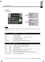
z
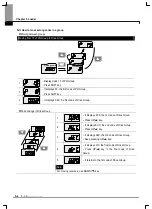
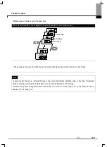
If setting frequency with volume resistance on the loader and commanding operation on the inverter’s terminal
No.
Indication
Operation & description
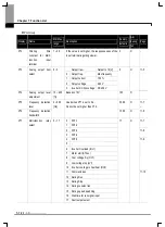
1
-. Target frequency, the first code of Drive Group when turning it on.
-. Press UP(
S
) key four times.
2
-. Moved to a code to change a frequency setting mode.
-. Press FUNC key.
3
-. The current frequency setting mode is set to 0(frequency setting using loader).
-. Press UP(
S
) key two times.
4
-. Check 3(frequency setting by loader’s volume resistance).
-. Press FUNC key.
-. 3 blinks quickly. Press FUNC key once more.
5
-. Frq is displayed and frequency setting mode is changed to loader volume.
-. Press SHFT moves to target frequency, the first code of Drive Group.
-. Turn the loader volume to MAX or MIN to set to 10.00Hz.
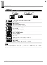
6
-. Turn on the switch between P1 (FX) and CM.
-. FWD(forward run) lamp of the inverter display blinks and accelerating frequency is
displayed on the LED.
-. When run frequency 10Hz is reached, the value is displayed as shown left.
-. Turn off the switch between P1 (FX) and CM terminals.
7
-. FWD(forward run) lamp of the inverter display blinks and decelerating frequency is
displayed on the LED.
-. When run frequency is reached to 0Hz, Run and FWD lamp turn off and target
frequency(10.00)is displayed
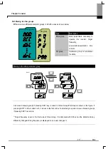
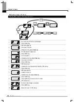
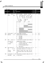
Wiring diagram
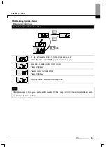
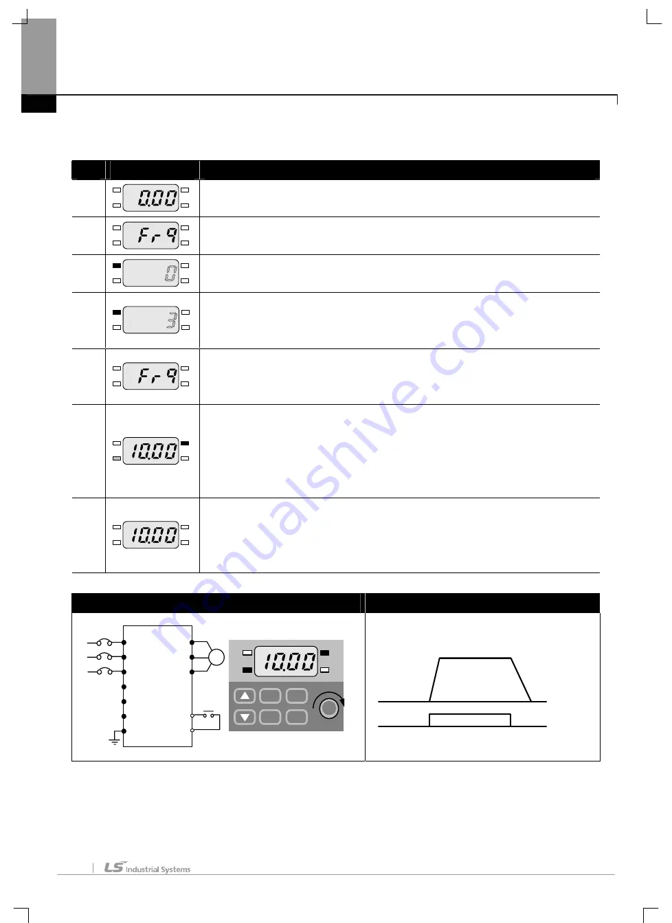
Operating pattern
M
L1 (R)
L2 (S)
(T)
P
P1
N
G
U
V
W
P1(FX)
CM
220 Vac
F U N C
S H F T
S T O P
R U N
Frequency
P1(FX)-CM
ON
OFF
10 Hz
Summary of Contents for SV-iE5 Series
Page 124: ...iV ...


