Right choice for ultimate yield
LSIS strives to maximize customers' profit in gratitude of choosing us for your
partner.
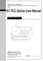
iS7 PLC Option User Manual
SV-iS7 PLC Option Card
z
Read this manual carefully before
installing, wiring, operating, servicing
or inspecting this equipment.
z
Keep this manual within easy reach
for quick reference.


