

Chapter 2 System Configuration
2-2
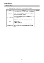
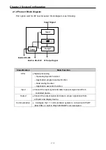
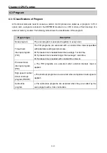
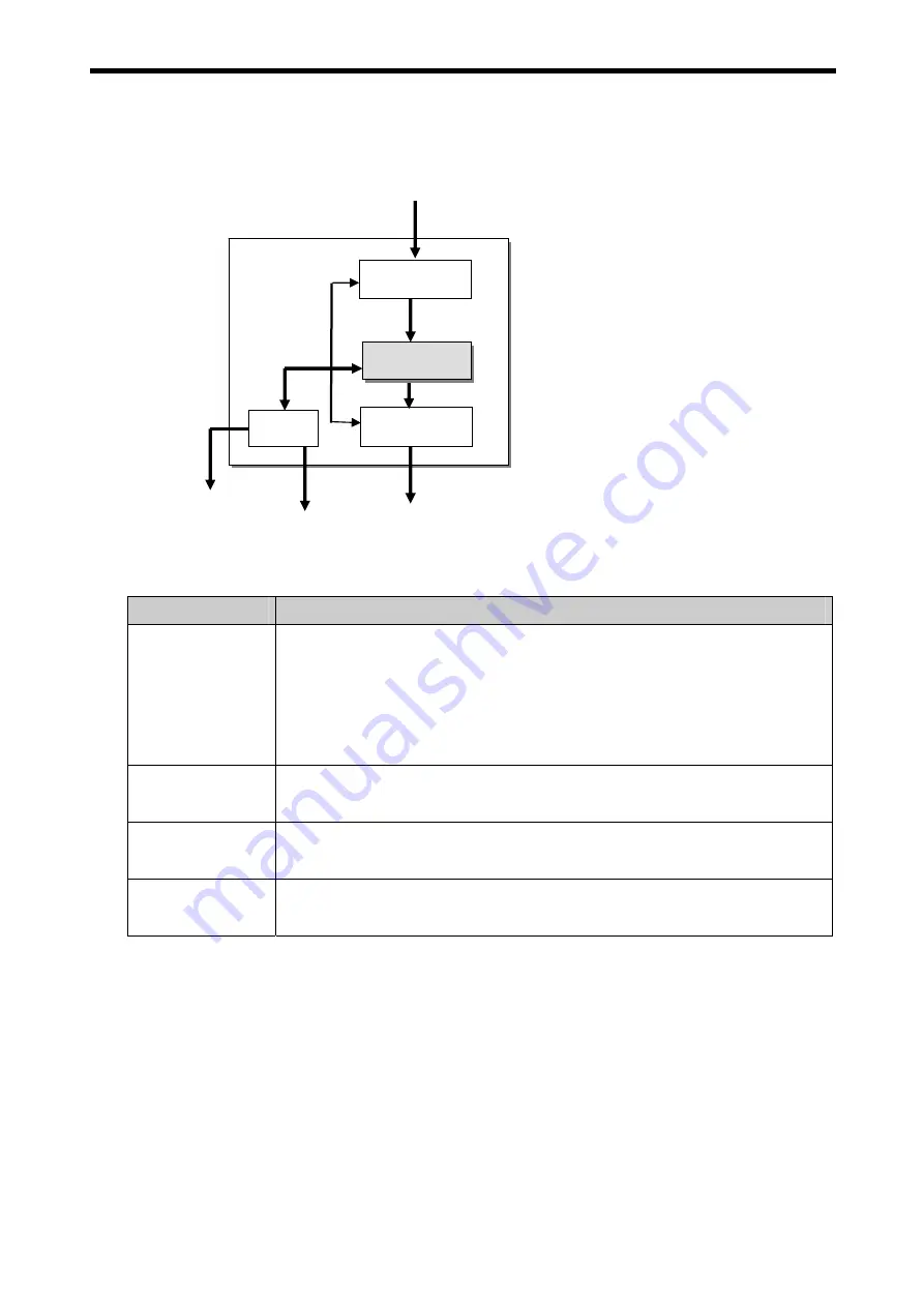
2.1.2 Product Block Diagram
PLC option card for iS7 inverter series’ block diagram is as following.
Input Signal
Built-in RS-232C I/F Output Signal
Classification
Main Function
CPU
•
Signal processing
-. Operating System function
-. Application program saving function
-. Data saving function
-. Application execution function
Input
•
Convert the input signal and data to proper signal level from
controlled device.
Output
•
Convert the output signal and data to proper signal level from
actuator and display device.
Communication
•
Configure the 1:1 communication system to connect with PADT
(KGLWIN) or built-in RS-232C/RS485 communication.
Comm
Input
Output
CPU
Built-in RS-485


