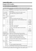
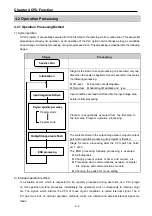
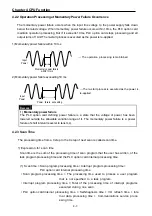


Chapter 4 CPU Function
4 - 7
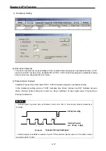
4.2.6 Counter Processing
The counter counts the rising edges of pulses driving its input signal and counts once only
when the input signal is switched from off to on. PLC option card have 4 counter instructions
such as Up Counter (CTU), Down Counter(CTD), Up/Down Counter (CTUD), and Ring
Counter (CTR). The followings shows brief information for counter operation.
•
Up Counter (CTU) increases the current value.
•
Down Counter (CTD) decreases the current value.
•
Up/Down Counter (CTUD) compares the 2 input conditions’ value.
•
Ring Counter (CTR) clear the current value as 0 when current value reaches to set value by
increasing the current value.
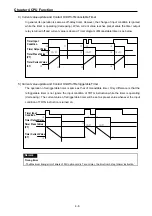
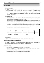
1) Current value update and Contact On/Off
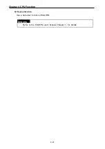
(1) Up Counter
•
Input Condition (U), Reset Condition (R), and preset value must be existed.
-. The counter output relay is turned on when the current value reaches the preset value.
-. When the reset input is turned on, the counter output relay and current value is cleared as 0.
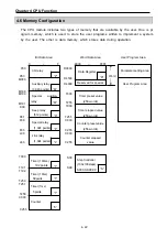
(2) Down Counter
•
Input Condition (U), Reset Condition (R), and preset value must be existed.
-. When reset signal is turned on, current value reaches to preset value and output relay is
turned off.
-. The counter output relay is turned on when the current value reaches 0.
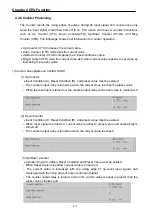
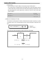
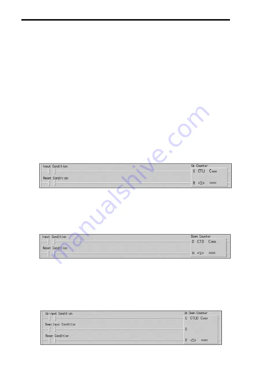
(3) Up/Down Counter
•
2 kinds of Input Condition, Reset Condition and Preset Value must be existed.
-. When Reset signal is inputted, current value is turned to 0.
-. The current value is increased with the rising edge of up-count input signal, and
decreased with the rising edge of down-count input signal.
-. The counter output relay is turned on when the current value is equal or greater than the
preset value otherwise off.


