


Chapter 7 Exclusive Functions for iS7 Inverter Control/Monitoring
7-5
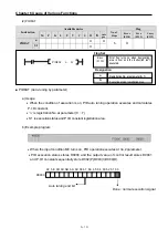
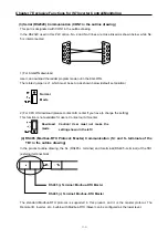
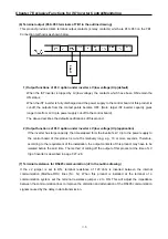
(5) Terminal input (P00~P05 terminals of TB1 in the drawing)
Total 6 terminal inputs are supported from P00~P05 on the external terminal block (TB1).
◆
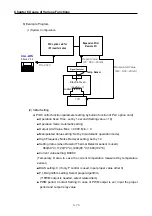
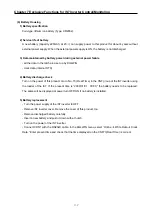
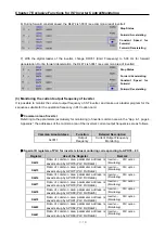
NPN (Sink) mode
1) Set the J3 (NPN/PNP selection jumper) as shown below.
2) Connect the wires to the external terminal block (TB1). The figure below shows PO connection only
for convenience (same for P1~P5 terminals).
◆
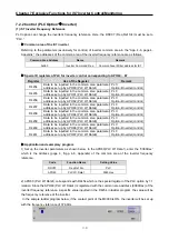
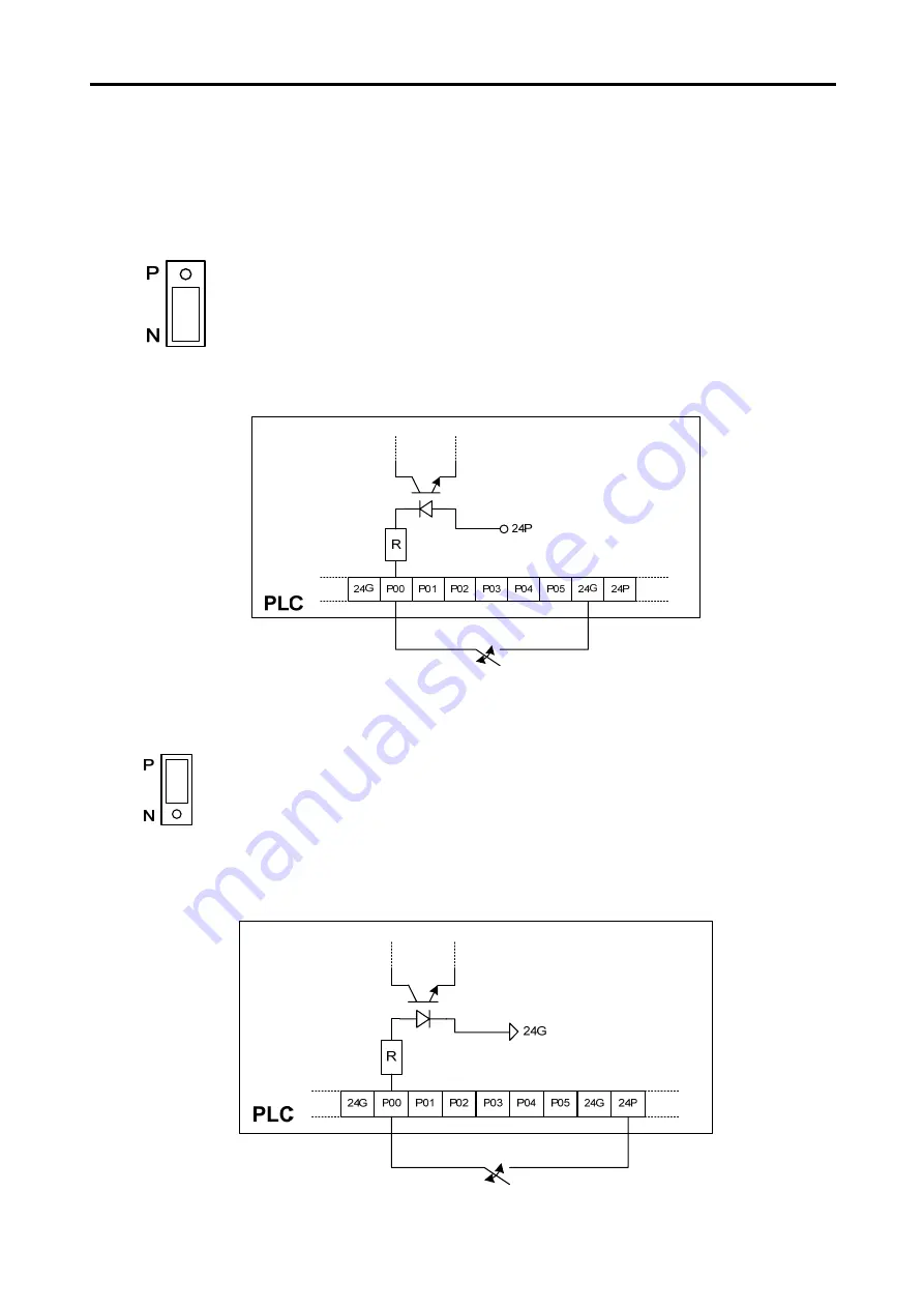
PNP (Source) Mode
1) Set up the J3 (NPN/PNP selection jumper) as shown below.
2) Connect the wires to TB1 as shown below. As illustrated, this product provides a 24V output from
the terminal block. In the figure below, the 24V output is used for PO connection (same for the P1~P5
terminals).
Terminal
inputs are in
NPN mode
External Switch
Terminal
inputs are in
PNP mode.
External Switch


