


Chapter 7 Exclusive Functions for iS7 Inverter Control/Monitoring
7-6
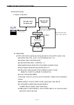
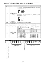
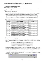
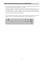
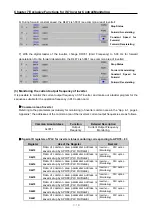
(6) Terminal output (P40~P43 terminals of TB1 in the outline drawing)
This product provides total 4 terminal output contacts (4 relay contacts) which are P40~P43 on the TB1.
Connection method is as shown below.
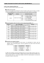
1) Output functions of PLC option under inverter LV (low voltage) trip (default)
When the iS7 inverter is tripped by LV(low voltage), the contacts which have been ON remain the
ON status.
When the iS7 inverter is fully discharged and the power supply to the control board of this product is
cut-off, the outputs from the contact points become OFF. (Note: larger iS7 inverter capacity gives
longer time from LV trip to power supply cut-off to the control board).
The above describes the default specifications of this product.
2) Output functions of PLC option under inverter LV (low voltage) trip (application)
If the inverter has large capacity, the time elapsed form the inverter’s LV trip to the power supply to
the control board of this product is cut-off is relatively long, e.g., 10 or more seconds. Therefore,
according to the requirement of the installation, the output contacts of this product may have to be
isolated before the said time. The method of cutting off the output of this product at the time of LV
trip of inverter is described in page 7-27~28.
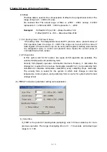
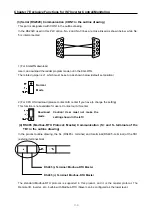
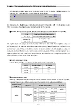
(7) Terminal resistance for RS485 communication (J2 in the outline drawing)
If the J2 jumper is set to ON, terminal resistance of 120 ohm is inserted between the internal
communication (Modbus-RTU) lines (S+, S-). When this product is installed at the terminal of a
communication system, set the terminal resistance jumper J2 to ON. This will adjust the impedance
between the communication lines to improve the distortion and attenuation of the RS485 communication
signals caused by the delay in data transmission.
Load


