


Chapter 8 Modbus Communication
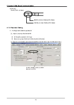
8-3
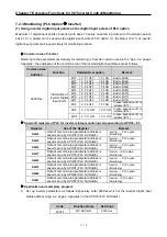
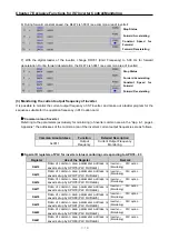
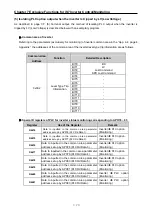
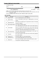
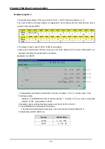
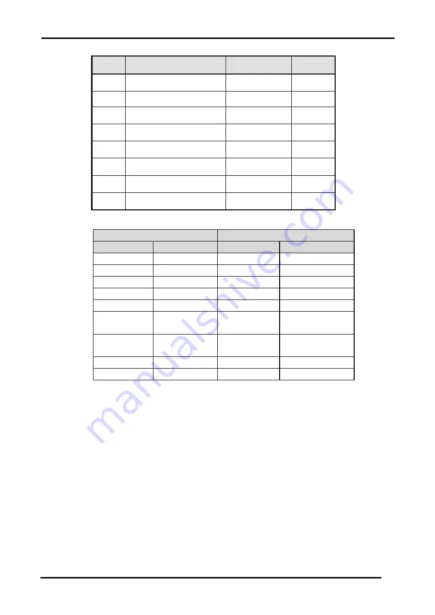
7) Function code type
Code
Function Code Name
Modicon PLC
Data Address
Remark
01
Read Coil Status
0XXXX(bit-
output)
Read bits
02
Read Input Status
1XXXX(bit-input)
Read bits
03
Read Holding Registers
4XXXX(word-
output)
Read
words
04
Read Input Registers
3XXXX(word-
input)
Read
words
05
Force Single Coil
0XXXX(bit-
output)
Write bit
06
Preset Single Register
4XXXX(word-
output)
Write word
15
Force Multiple Coils
0XXXX(bit-
output)
Write bits
16
Preset Multiple Registers
4XXXX(word-
output)
Write
words
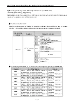
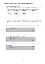
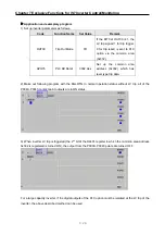
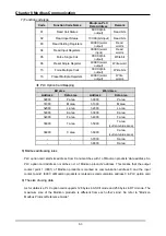
◈
PLC Option Card Mapping
Bit area
Word area
Address
Data area
Address
Data area
h0000
P area
h0000
P area
h1000
M area
h1000
M area
h2000
L area
h2000
L area
h3000
K area
h3000
K area
h4000
F area
h4000
F area
h5000 T
area h5000
T area
(current value area)
h6000 C
area h6000
C area
(current value area)
- -
h7000
S
area
- -
h8000
D
area
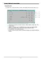
8) Modbus addressing rules
PLC option card starts its address from 0 and matches with 1 of Modicon products' data address. So
PLC option card address n matches n+1 of Modicon products' address. This means that the output
contact point 1 (0001) of Modicon products is marked as communication address 0 and the input
contact point 1 (0001) of Modicon products is marked as communication address 0 in PLC option card.
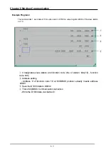
9) The size of using data
As for data size, PLC option card supports 128 bytes in ASCII mode and 256 bytes in RTU mode. The
maximum size of the Modicon products is different from each other’s kind. So refer to "Modicon
Modbus Protocol Reference Guide."


