


Chapter 6 Instruction Details
XBC E-Type Main Unit
6-79
Ver. 1
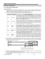
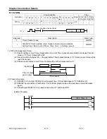
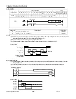
6.18.2 CTD
Instruction
Area Available
Step
Flag
P M K F L T C S Z D.x R.x
Co
nst.
U N D R
Error
(F110)
Zero
(F111)
Carry
(F112)
CTD
C
-
-
-
-
-
- O -
-
-
-
-
-
-
-
-
2/3
-
-
-
N O O O -
-
-
-
-
-
-
- O O - O O
Operand
Description
Data Type
C
Counter contact to use
WORD
N
Set Value (0 ~ 65535)
WORD
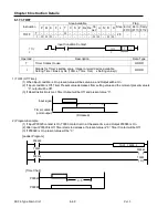
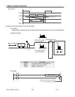
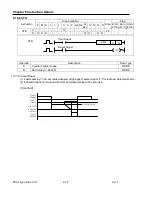
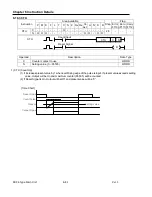
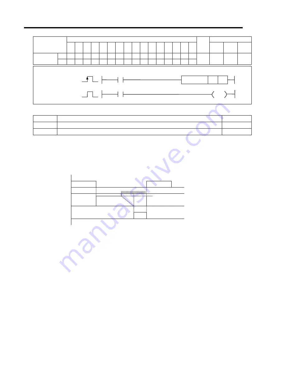
1) CTD (Count Down)
(1) It decreases by 1 from set value whenever rising edge of pulse is input. If “0” is reached, Output will be On.
(2) If Reset Signal is On, Output will be Off, and present value will be set value.
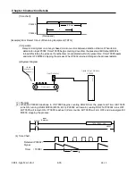
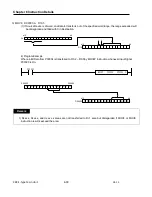
[Time Chart]
Reset
Signal
Present
Setting value
Count
Input
Counter
contact
point
Output
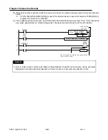
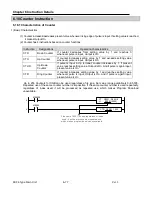
Reset Signal
CTD
Count Input
CTD
C
N
R
Summary of Contents for XBC-DN10E
Page 1: ......
Page 10: ...Table of Contents Table of Contents 6 10 10 CLEAR ALL PLC 29...


