


Chapter 4 CPU Specifications
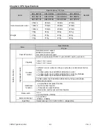
XBC E-Type Main Unit
4-12
Ver. 1
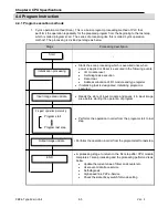
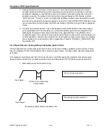
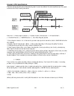
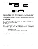
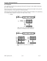
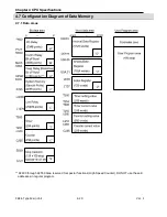
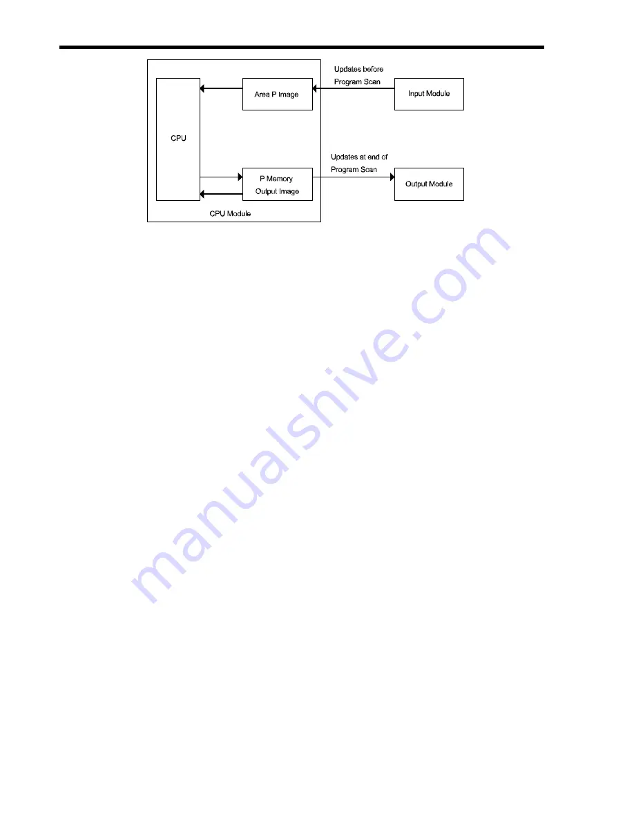
As shown above, the P Area image is updated prior to the program scan. After the program logic is solved, the P
Area Image is again updated. When the P Area image is updated prior to the next program scan, the output
status from the end of the previous scan is also updated.
Inputs and Outputs are both assigned to the P Area image. Use caution when programming to prevent conflicts
between Inputs and Outputs.
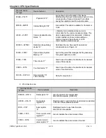
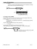
4.5.4 Auxiliary relay M
M Bits are internal relays to be used in the program. There are designated as a bit within a word in Hex format.
For example, Word M200 Bits 0 through F. Unless set as Retentive (Latch), M Bits are reset to OFF during a
power cycle or a Stop to Run PLC Mode change.
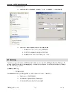
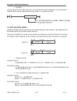
4.5.5 Keep relay K
K Bits are retentive internal relays to be used in the program. They are designated in a bit within a word in Hex
format. For example, Word K000 bits 0 through F. The K Bits states are not changed by a power cycle, Stop to
Run mode change, or a program download. Unless controlled by the PLC program, only an Overall Reset of the
PLC or deletion of the program will reset the K Bits. The K Bit values can be altered in the Device monitoring
function. Use extreme caution when using the K Bits in your program.
1. Deleting the existing program
2. Using a function to delete memory of the PLC delete menu in XG5000.
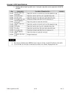
4.5.6 Link relay L
The L Bits (Link Relay) are internal flag bits when using communication modules. The flag bits are described in
the XG5000 software.
Summary of Contents for XBC-DN10E
Page 1: ......
Page 10: ...Table of Contents Table of Contents 6 10 10 CLEAR ALL PLC 29...


