


Chapter 4 CPU Specifications
XBC E-Type Main Unit
4-21
Ver. 1
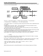
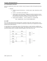
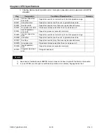
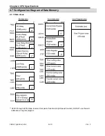
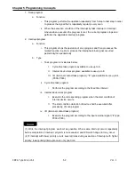
4.7.2 Data latch
When PLC stops and restarts, the data required for operation or data occurred during operation, will be lost by
default. If you want to keep and use that data, data latch can be used. It is possible to use a certain area of
some data device as latch area by parameter setting.
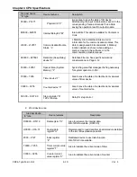
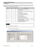
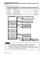
Device
1
st
latch
2
nd
latch
Features
P
X
X
Image area to save the state of I/O device
M
O
O
Internal device area
K
X
X
Device keeping the device state during power shutdown
F
X
X
System flag area
T
O
O
Timer related area (Bit/words both)
C
O
O
Counter related area (Bit/words both)
S
O
O
Relay for step control
D
O
O
General words data save area
U
X
X
Analog Data Register (latch disabled )
L
X
X
High speed link/P2P Service state device of communication
module (latch enabled)
Z
X
X
Index dedicated Register (latch disabled)
R
O
O
File register (latch enabled)
Remark
▪ K, L, R devices are retentive (latched).
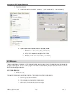
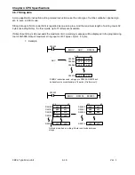
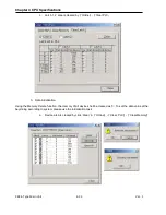
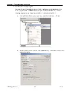
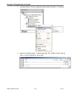
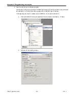
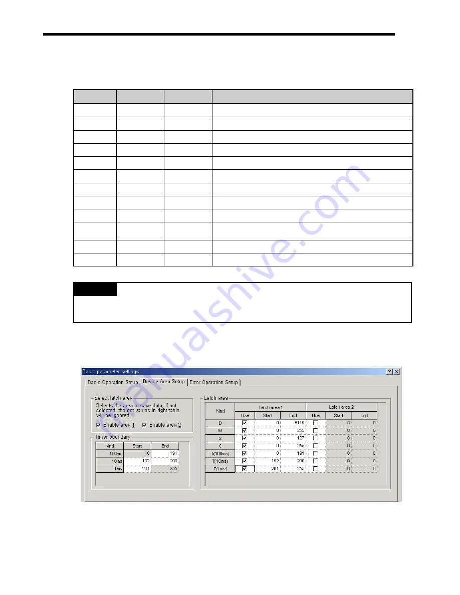
1. Retentive memory (Latch area) settings
a. Click Device Area Setup of Basic parameter settings and check the areas to latch.
Summary of Contents for XBC-DN10E
Page 1: ......
Page 10: ...Table of Contents Table of Contents 6 10 10 CLEAR ALL PLC 29...


