

Right choice for ultimate yield
LSIS strives to maximize customers' profit in gratitude of choosing us for your partner.
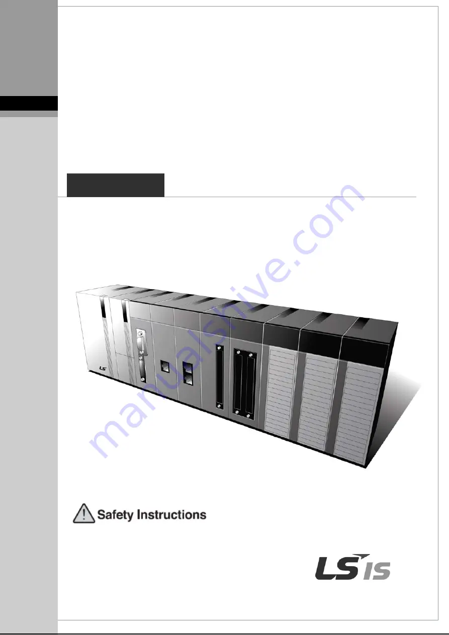
Programmable Logic Controller
XGB Pnet I/F Module
User’s Manual
Read this manual carefully before
installing, wiring, operating, servicing
or inspecting this equipment.
Keep this manual within easy reach
for quick reference.
XBL-PMEC
XGT Series
http://www.lsis.com
Summary of Contents for XBL-PMEC
Page 50: ...Chapter 5 PROFICON Setting 5 18 Figure 5 4 8 Network topology collected and composed...
Page 84: ...Chapter 7 Program Example 7 12 Figure 7 3 3 Screen of communication module setting...
Page 91: ...Chapter 8 Troubleshooting 8 3 8 5 Troubleshooting 8 5 1 Connection error on PROFICON XG5000...
Page 99: ...Appendix A 7 A 4 External Dimensions Unit mm XBL PMEC XBL PMEC...


