4. Parameters
4-54
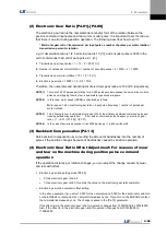
=> Encoder pulse output: 3,000 [ppr] × 1/2 = 1,500 [ppr]
14.
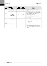
PWM OFF delay time setting [P0-16]
Sets the time span between servo OFF command and actual PWM OFF. This is to prevent the
motor from slipping down the vertical axis until the motor brake comes into effect after receiving the
servo off command and then the brake signal. Set a PWM off delay when operating the motor brake
with the output contact point brake signal. (Range: 0-1000 [ms]. Initial value: 10.)
15.
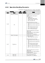
DB control mode [P0-17]: Sets DB control mode.
0: Hold after DB stop
1: Release after DB stop.
2: Release after free run stop.
3: Hold after free run stop.
16.
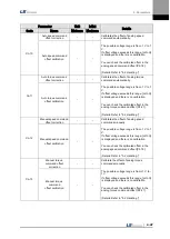
Servo function setting bit [P0-18]
Sets drive function per digit.
DIGIT 1 -> Sets the operation direction of the servo.
0: CCW (Forward), CW (Reverse)
1: CW (Forward), CCW (Reverse)
DIGIT 2 -> Sets the open collector output.
0: Not for use
1 : Use(AL0,AL1,AL2 output contact point
open collector A,B,Z output)
DIGIT 4 -> Sets the monitor output.voltage.(can be applied both monitor1 and 2)
0: -10~+10V
1 : 0~+10V
17.
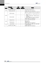
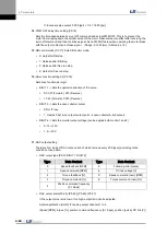
DAC output setting
There are four kinds of DAC output, each of which is made every 200 [usec] according to the
condition of used data.
DAC output type [P0-19 DIGIT 1, DIGIT 2]
Type
Data Content
Type
Data Content
0
Speed feedback [RPM]
5
Following error [pulse]
1
Speed command [RPM]
6
DC link voltage [V]
2
Torque feedback [%]
D
Speed command (user) [RPM]
3
Torque command [%]
E
Torque command (user) [%]
4
Position command frequency
[0.1 Kpps]
DAC output scale[P0-24], [P0-25], [P0-26], [P0-27]
If the output value is too low or too high, output ratio can be adjusted.
Sets magnification [Unit/V] for analog output channels 1 to 4.
(Speed [RPM], torque [%], position command frequency [0.1 Kpps], position [pulse], DC link [V])
Summary of Contents for L7 A001
Page 1: ...VER 1 5...
Page 2: ......
Page 32: ...1 Product Components and Signals 1 20...
Page 38: ...2 Installation 2 6...
Page 54: ......
Page 188: ...7 Product Specifications 7 26 L7 A020 L7 A035 Weight 2 5 kg cooling fan included...
Page 210: ...8 Maintenance and Inspection 8 14...
Page 211: ...9 Appendix 9 1 9 Appendix...
Page 218: ...9 Appendix 9 8...
Page 221: ......
Page 222: ......

