1. Product Components and Signals
1-9
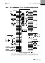
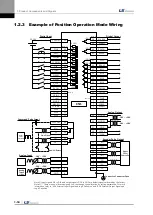
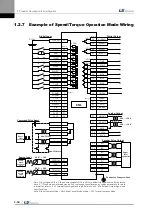
1.2.2
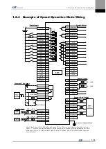
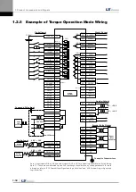
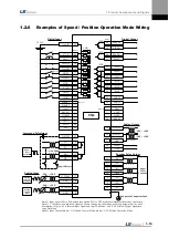
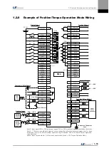
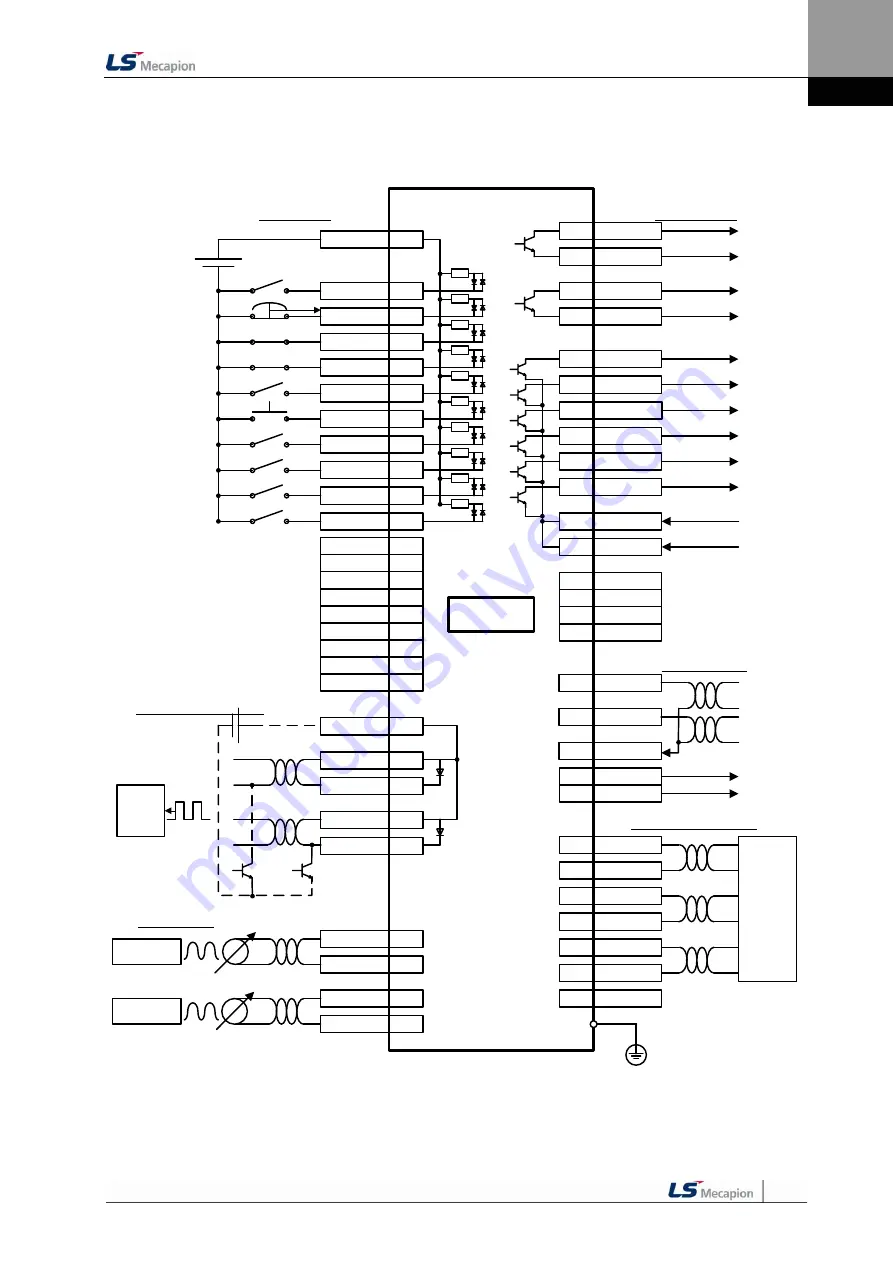
Wiring Diagram of the Entire CN1 Connector
STOP
48
EMG
18
CWLIM
19
CCWLIM
20
DIR
46
ALMRST
17
SPD3
21
SPD2
22
SPD1
23
SVON
47
ALARM+
38
ALARM-
39
READY+
40
READY-
41
ZSPD
43
BRAKE
44
INPOS
45
50
+24V IN
GND24
24
ALO0
16
ALO1
15
ALO2
14
GND24
25
SPDCOM
27
GND
8
TRQCOM
1
GND
8
Digital Input
Digital Output
Command Pulse Input
Analog Input
DC 24V
3.3kΩ
Line Driver
Open Collector
CN1
-10V ~ +10V
Upper Level
Controller
-10V ~ +10V
Analog Speed
Command/Limit
Analog Torque
Command/Limit
Note 1)
(DIA)
(DI9)
(DI8)
(DI7)
(DI6)
(DI5)
(DI4)
(DI3)
(DI2)
(DI1)
(DO1)
(DO2)
(DO3)
(DO4)
(DO5)
Note 1)
Note 1) Input signals DI1 to DIA and output signals DO1 to DO5 are default signals allocated by the factory.
Note 2) ** These are non-allocated signals. You can change their allocation by setting parameters. For more
information, refer to “4.1.6 External Input Signal and Logic Definition” and “4.1.8 External Output Signal and
Logic Definition.”
VLMT
**
TLMT
**
Note 2)
WARN
**
INSPD
**
EGEAR1
**
EGEAR2
**
PCON
**
GAIN2
**
P_CLR
**
T_LMT
**
Note 2)
MODE
**
ABS_RQ
**
ZCLAMP
**
MONIT1
28
MONIT2
29
GND
37
AO
32
/AO
33
BO
30
/BO
31
ZO
4
/ZO
5
SG
36
Analog Output
Encoder Pulse Output
Connect to Connector Case
-10V ~ +10V
-10V ~ +10V
Upper Level
Controller
+12VA
34
-12VA
35
PULCOM
49
PF+
9
PF-
10
PR+
11
PR-
12
Summary of Contents for L7 A001
Page 1: ...VER 1 5...
Page 2: ......
Page 32: ...1 Product Components and Signals 1 20...
Page 38: ...2 Installation 2 6...
Page 54: ......
Page 188: ...7 Product Specifications 7 26 L7 A020 L7 A035 Weight 2 5 kg cooling fan included...
Page 210: ...8 Maintenance and Inspection 8 14...
Page 211: ...9 Appendix 9 1 9 Appendix...
Page 218: ...9 Appendix 9 8...
Page 221: ......
Page 222: ......


