background image


3. Wiring Method 


3-13


3.6


Serial Encoder Signaling Unit (CN2) 
Wiring 

3.6.1


APCS-E



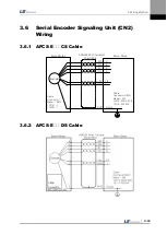
CS Cable 


Encoder


1  
2  
3  
4  


7  
8  


9  

MA 


SL 

/SL 


+5V 
GND


SHD 


3  
4  
5  
6  


14 
7  


Frame 


Servo Drive


Servo Motor


AWG24 4Pair Twisted

Shield Wire 

Cable 
Connector
Maker - AMP
172161-1
170361-1

Cable
Connector(CN2)
Maker 

 3M

10314-52A0-008
10114-3000VE

/MA


3.6.2


APCS-E



DS Cable 


Summary of Contents for L7 A001

Page 1: ...VER 1 5...

Page 2: ......

Page 3: ...guidelines The contents of this manual are subject to change without prior notice depending on software versions No reproduction of part or all of the contents of this manual in any form by any means...

Page 4: ...nutes until the charge lamp goes off and then check the voltage Be sure to ground both the servo drive and the servo motor Only specifically trained professional engineers are permitted to perform wir...

Page 5: ...ocation free from iron corrosive gas and combustible gas Install in a location free from vibration or shock Caution Make sure that the installation orientation is correct Do not drop the product or ex...

Page 6: ...ire for the pulse command signal PF PF PR PR speed command signal SPDCOM and torque command signal TRQCOM Precautions for Initial Operation Caution Check the input voltage AC 200 230 V and power unit...

Page 7: ...ke or separately install a brake system on the outside In case of an alarm solve the source of the problem After you solve the problem and ensure safety deactivate the alarm and start operation again...

Page 8: ...s for the purpose of among others recording parameter settings The servo drive may malfunction depending on the lifespan of EEPROM when the total counts of the following tasks exceed 1 million EEPROM...

Page 9: ...put Contact Signal 1 16 1 3 2 Analog Input Contact Signal 1 17 1 3 3 Digital Output Contact Signal 1 17 1 3 4 Monitor Output Signal and Output Power 1 18 1 3 5 Pulse Train Input Signal 1 18 1 3 6 Enco...

Page 10: ...on 4 11 4 1 7 External Output Contact Signal Display St 15 4 19 4 1 8 External Output Signal and Logic Definition 4 20 4 2 Parameter Description 4 26 4 2 1 Parameter System 4 26 4 2 2 Operation Status...

Page 11: ...que Command Offset Correction Cn 11 5 15 5 2 13 Manual Speed Command Offset Correction Cn 12 5 16 5 2 14 Manual Torque Command Offset Correction Cn 13 5 17 5 2 15 Instantaneous Maximum Load Factor Ini...

Page 12: ...ance and Inspection 8 1 8 1 1 Precautions 8 1 8 1 2 What to Inspect 8 1 8 1 3 Parts Replacement Cycle 8 2 8 2 Diagnosis of Abnormality and Troubleshooting 8 3 8 2 1 Servo Motor 8 3 8 2 2 Servo Drive 8...

Page 13: ...al or brake is mounted Are the gearbox and the gear ratios correct Is the encoder format correct 3 Check the exterior Is there any foreign substance or humidity Is there any discoloring contamination...

Page 14: ...haft H Hollow Shaft B Assembly F Flat Type Flange Size A 40 Flange B 60 Flange C 80 Flange D 100 Flange E 130 Flange F 180 Flange G 220 Flange H 250 Flange J 280 Flange Rated RPM A 3000 RPM D 2000 RPM...

Page 15: ...ype 130 Flange or higher Bearing Cap Shaft Flange Frame Housing Encoder Cover Encoder Connector Motor Power Cable Motor Connector Encoder Cable Bearing Cap Shaft Flange Frame Housing Encoder Cover Enc...

Page 16: ...inals When installing external resistance install in the B and B terminals Motor power cable connector U V W Operation keys Mode Up Down Set Heat sink Control power connector C1 C2 Ground CN3 RS 422 c...

Page 17: ...ommunication connector Main power connector L1 L2 L3 Motor power cable connector U V W Heat sink Control power connector C1 C2 Ground Operation keys Mode Up Down Set DC reactor connector PO PI Short c...

Page 18: ...communication connector Main power connector L1 L2 L3 Motor power cable connector U V W Heat sink Control power connector C1 C2 DC reactor connector PO PI Short circuit when not used Regenerative resi...

Page 19: ...Motor Motor Encoder Position Feedback Advantage The structure of the upper level controller is simple because pulse input is linked to transfer units Disadvantages Fast rotation is compromised when a...

Page 20: ...Mode The L7 servo drive can be run in torque speed and position modes depending on its interface with the upper level controller The operation modes can be switched by parameters or digital input con...

Page 21: ...Note 1 DIA DI9 DI8 DI7 DI6 DI5 DI4 DI3 DI2 DI1 DO1 DO2 DO3 DO4 DO5 Note 1 Note 1 Input signals DI1 to DIA and output signals DO1 to DO5 are default signals allocated by the factory Note 2 These are no...

Page 22: ...Input Connect to Connector Case DC 24V 3 3k Line Driver Open Collector CN1 10V 10V 10V 10V 10V 10V Upper Level Controller 10V 10V Analog Torque Limit Upper Level Controller EGEAR1 EGEAR2 PCON GAIN2 P...

Page 23: ...e Limit Note 1 DIA DI9 DI8 DI7 DI6 DI5 DI4 DI3 DI2 DI1 DO1 DO2 DO3 DO4 DO5 Note 1 Note 1 Input signals DI1 to DIA and output signals DO1 to DO5 are default signals allocated by the factory Note 2 Thes...

Page 24: ...Command Note 1 DIA DI9 DI8 DI7 DI6 DI5 DI4 DI3 DI2 DI1 DO1 DO2 DO3 DO4 DO5 Note 1 Note 1 Input signals DI1 to DIA and output signals DO1 to DO5 are default signals allocated by the factory Note 2 Thes...

Page 25: ...DI8 DI7 DI6 DI5 DI4 DI3 DI2 DI1 DO1 DO2 DO3 DO4 DO5 Note 1 Note 1 Input signals DI1 to DIA and output signals DO1 to DO5 are default signals allocated by the factory Note 2 These are non allocated sig...

Page 26: ...6 DI5 DI4 DI3 DI2 DI1 DO1 DO2 DO3 DO4 DO5 Note 1 Note 1 Input signals DI1 to DIA and output signals DO1 to DO5 are default signals allocated by the factory Note 2 These are non allocated signals You c...

Page 27: ...I9 DI8 DI7 DI6 DI5 DI4 DI3 DI2 DI1 DO1 DO2 DO3 DO4 DO5 Note 1 Note 1 Input signals DI1 to DIA and output signals DO1 to DO5 are default signals allocated by the factory Note 2 These are non allocated...

Page 28: ...DIR Select rotation direction O O O O O O 20 CCWLMT Counter clockwise limit O O O O O O 19 CWLMT Clockwise limit O O O O O O 18 EMG Emergency stop O O O O O O 48 STOP Stop O O O O O O Allocate EGEAR1...

Page 29: ...f Factory Setting Name Description Applicable Modes Position Speed Torque Speed Position Speed Torque Position Torque 16 ALO0 Alarm group contact output 1 O O O O O O 15 ALO1 Alarm group contact outpu...

Page 30: ...O O O 1 3 5 Pulse Train Input Signal Line Driver 5 V Pin Number Name Description Applicable Modes Position Speed Torque Speed Position Speed Torque Position Torque 9 PF F pulse input O X X X O X O X...

Page 31: ...ed Torque Speed Position Speed Torque Position Torque 32 33 30 31 AO AO BO BO Outputs encoder signals received from the motor as signals pre scaled according to the ratio defined by P0 14 P0 15 5 V li...

Page 32: ...1 Product Components and Signals 1 20...

Page 33: ...k Excessive shock to the motor shaft during installation or the motor falling during handling may damage the encoder 2 1 3 Motor Connection The motor might burn out when commercial power is directly c...

Page 34: ...60 206 21 69 7 80 255 26 98 10 130 725 74 362 37 180 1548 158 519 53 220 1850 189 781 90 2 1 5 Cable Installation In case of vertical installation make sure that no oil or water flows into connection...

Page 35: ...on or freezing of moisture inside the drive during prolonged periods of inactivity may damage it Remove any moisture completely before you operate the drive after a prolonged period of inactivity Exte...

Page 36: ...re that it is sufficiently close to the wall When assembling the control panel make sure that metal powder caused by drilling does not enter the drive Make sure that oil water and metal dust do not en...

Page 37: ...ity Notes L7 A001 100 Built in 50 W Caution For more information about resistance for expanding regenerative capacity refer to 7 3 Option and Peripheral Device L7 A002 L7 A004 L7 A08 40 Built in 100 W...

Page 38: ...2 Installation 2 6...

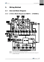
Page 39: ...l Block Diagram 3 1 1 L7 Drive Block Diagram L7SA001 L7SA004 NOTE 1 If you use a DC reactor connect to the PO and PI pins NOTE 2 If you use external regenerative resistance connect to the B and B pins...

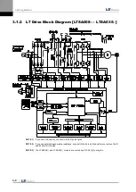
Page 40: ...NOTE 1 If you use a DC reactor connect to the PO and PI pins NOTE 2 If you use external regenerative resistance connect to the B and B pins after you remove the B and BI short circuit pins NOTE 3 The...

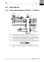
Page 41: ...50 W 100 L7SA010 100 W 40 and L7SA035 150 W 13 exist inside If regenerative capacity is high because of frequent acceleration and deceleration open the short circuit pins B BI and connect external re...

Page 42: ...24 A Noise Filter NF RFY 4010M 4020M 4030M DC reactor HFN 6 6 A HFN 10 10 A HFN 30 30 A MC GMC 9 11 A GMC 18 18 A GMC 40 35 A Wire AWG16 1 25 SQ AWG14 2 0 SQ AWG12 4 0 SQ Crimp terminal UA F1510 SEOIL...

Page 43: ...o the main circuit The servo signal becomes Ready after the maximum time of 120 ms that is required to reset the inside of the device If you change the signal to ON the servo starts operation in 40 ms...

Page 44: ...re you solve the problem that triggered the alarm and change the command signal Servo ON to OFF 200 ms Control power establishment 5 V Control program Reset Main power establishment Alarm Normally On...

Page 45: ...contact A and contact B They can be set by P2 08 and P2 09 2 It is possible to turn each contact on or off forcibly with Cn 07 Take extra caution however because each contact is automatically turned o...

Page 46: ...h Cn 08 Take extra caution however because each contact is automatically turned off when power is off 5 The signal definition of each contact point can be modified by P2 05 P2 06 and P2 07 6 Overvolta...

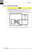
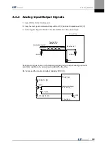
Page 47: ...nitor 1 No 28 and Monitor 2 No 29 is 10 V Configure wiring as shown in the following image when you adjust analog input with parameter resistance by using power supplied by the drive Do not exceed the...

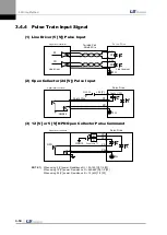
Page 48: ...Resistance R 100 150 1 2 W When using 12 V power Resistance R 560 680 1 2 W When using 24 V power Resistance R 1 5 k 1 2 W Servo Drive Upper level controller PF PR PF PF PR PR Line driver Line receiv...

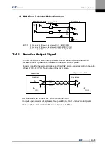
Page 49: ...output based on the GND of control power Encoder signals for the servo motor received from CN2 are pre scaled according to the ratio defined by P0 14 P0 15 and output in line driver mode Set bit numb...

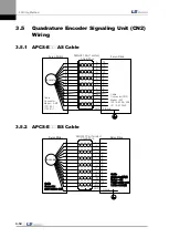
Page 50: ...Servo Motor AWG24 7Pair Twisted Shield Wire Cable Connector Maker AMP 172163 1 170361 1 Cable Connector CN2 Maker 3M 10314 52A0 008 10114 3000VE 3 5 2 APCS E BS Cable Servo Drive Servo Motor Encoder A...

Page 51: ...3 6 1 APCS E CS Cable Encoder 1 2 3 4 7 8 9 MA SL SL 5V GND SHD 3 4 5 6 14 7 Frame Servo Drive Servo Motor AWG24 4Pair Twisted Shield Wire Cable Connector Maker AMP 172161 1 170361 1 Cable Connector...

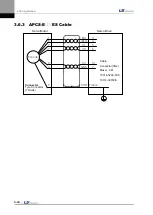
Page 52: ...thod 3 14 3 6 3 APCS E ES Cable Servo Drive Servo Motor 1 6 2 7 9 4 5 MA MA SL SL 5V GND SHD Cable Connector CN2 Maker 3M 10314 52A0 008 10114 3000VE Connector Tyco Connector 7Ciruits Encoder 3 4 5 6...

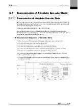
Page 53: ...f the sequence input signal and ABS RQ signal Transmission Sequence of Absolute Data 1 When the servo is off change the ABS_RQ signal on the upper level controller to ON 2 The servo drive checks the A...

Page 54: ......

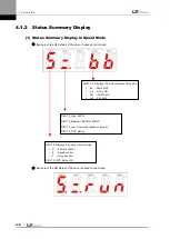
Page 55: ...4 Digit 3 Digit 2 Digit 1 MODE Change display mode LEFT Move to another data digit UP Increase displayed data DOWN Decrease displayed data SET Confirm displayed data RIGHT Move to another data digit...

Page 56: ...status of the servo in speed control mode DIGIT 3 1 Displays the current status of the servo bb Servo OFF run Servo ON Pot CCW Limit not CW Limit DIGIT 4_High ZSPD DIGIT 4_Medium INSPD or INPOS DIGIT...

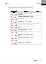
Page 57: ...s ON status when in position mode Displays CCW status when in position mode Displays CW status when in position mode Displays the servo s OFF status when in speed mode Displays the servo s ON status w...

Page 58: ...P4 11 P4 12 P4 13 Operation Status Summary Display P1 00 P2 00 P3 00 P1 25 P2 22 P3 20 If the alarm does not go off at the start of operation the speed operation mode S bb indicating operation status...

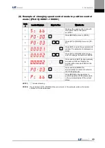
Page 59: ...isplayed as 00001 5 Press UP or DOWN at the blinking cursor to change the number to 00002 6 Press and hold SET for approximately one second After two flickers the number will be saved as 00002 in the...

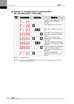
Page 60: ...meter is displayed as 00200 5 Press LEFT or RIGHT at the blinking cursor to move to the desired digit DIGIT 3 6 Press UP or DOWN at the blinking DIGIT 3 position to change the number to 00500 7 Press...

Page 61: ...ter is displayed as 00000 5 Press LEFT or RIGHT at the blinking cursor to move to the desired digit DIGIT 3 6 Press UP or DOWN at the blinking DIGIT 3 position to change the number to 0500 7 Press and...

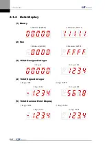
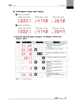
Page 62: ...ry Minimum 0b00000 Maximum 0b11111 2 Hex Minimum 0x0000 Maximum 0xFFFF 3 16 bit Unsigned Integer E g 0 E g 1234 4 16 bit Signed Integer E g 1234 E g 5678 E g 1234 E g 5678 5 16 bit Decimal Point Displ...

Page 63: ...d Lower 2071 Order Loader Displays Keys to Use What to Do 1 Displays the speed control mode with main power and control power permitted 2 Press MODE to move to St 00 3 Press UP or DOWN to move to St 1...

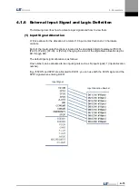
Page 64: ...play The positions of the seven segment LEDs and CN1 connector pins correspond as follows If an LED that corresponds to a pin is turned on off it indicates ON OFF accordingly Input Contact Display Num...

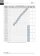
Page 65: ...nput contact functions is located at the designated digit of parameter P2 00 P2 01 P2 02 P2 03 or P2 04 Changing the value of the digit allows allocation to pins DI1 through DIA The default input sign...

Page 66: ...on prohibited P2 01 Set Digit 4 CWLIM F A 9 8 7 6 5 4 3 2 1 0 Emergency stop P2 02 Set Digit 1 EMG F A 9 8 7 6 5 4 3 2 1 0 P2 02 0x00A9 Stop P2 02 Set Digit 2 STOP F A 9 8 7 6 5 4 3 2 1 0 Electronic g...

Page 67: ...Allocation The input signal definition can be changed in P2 00 P2 01 P2 02 P2 03 and P2 04 The input signal logic definition can be changed in P2 08 and P2 09 Allocate input signals as shown in the f...

Page 68: ...ation prohibited P2 01 Set Digit 4 CWLIM F A 9 8 7 6 5 4 3 2 1 0 Emergency stop P2 02 Set Digit 1 EMG F A 9 8 7 6 5 4 3 2 1 0 P2 02 0x0080 Stop P2 02 Set Digit 2 STOP F A 9 8 7 6 5 4 3 2 1 0 Electroni...

Page 69: ...for the parameter 5 Hold down MODE for approximately one second to return to P2 00 6 Press UP or DOWN at the blinking cursor to change the number to P2 02 7 Press SET to enter parameter edit mode The...

Page 70: ...Servo ON P2 08 Set Digit 1 SVON 1 0 P2 08 0x11111 Multi speed 1 P2 08 Set Digit 2 SPD1 1 0 Multi speed 2 P2 08 Set Digit 3 SPD2 1 0 Multi speed 3 P2 08 Set Digit 4 SPD3 1 0 Alarm reset P2 08 Set Digit...

Page 71: ...t Digit 1 SVON 1 0 P2 08 0x11111 Multi speed 1 P2 08 Set Digit 2 SPD1 1 0 Multi speed 2 P2 08 Set Digit 3 SPD2 1 0 Multi speed 3 P2 08 Set Digit 4 SPD3 1 0 Alarm reset P2 08 Set Digit 5 ALMRST 1 0 Sel...

Page 72: ...After two flickers the number is saved as 11110 for the parameter 5 Hold down MODE for approximately one second to return to P2 08 6 Press UP or DOWN at the blinking cursor to change the number to P2...

Page 73: ...off 1 External Output Signal Display The positions of the seven segment LEDs and CN1 connector pins correspond as follows If an LED that corresponds to a pin is turned on off it indicates ON OFF acco...

Page 74: ...ameter Allocation 45 44 43 40 41 38 39 Alarm P2 05 Set Digit 1 ALARM F 5 4 3 2 1 0 P2 05 0x4321 Servo Ready P2 05 Set Digit 2 READY F 5 4 3 2 1 0 Zero speed achieved P2 05 Set Digit 3 ZSPD F 5 4 3 2 1...

Page 75: ...8 39 Alarm P2 05 Set Digit 1 ALARM F 5 4 3 2 1 0 P2 05 0x0301 Servo Ready P2 05 Set Digit 2 READY F 5 4 3 2 1 0 Zero speed achieved P2 05 Set Digit 3 ZSPD F 5 4 3 2 1 0 Brake P2 05 Set Digit 4 BRAKE F...

Page 76: ...e number to 04323 4 Press LEFT or RIGHT at the blinking cursor to move to the desired digit DIGIT 3 5 Press UP or DOWN at the blinking cursor to change the number to 04123 6 Hold down SET for approxim...

Page 77: ...on 45 44 43 40 41 38 39 Alarm P2 10 Set Digit 1 ALARM 0 P2 10 0x10110 Servo Ready P2 10 Set Digit 2 READY 1 0 Zero speed achieved P2 10 Digit 3 ZSPD 1 0 Brake P2 10 Digit 4 BRAKE 0 Position reached P2...

Page 78: ...Setting Parameter Allocation 45 44 43 40 41 38 39 Alarm P2 10 Set Digit 1 ALARM 0 P2 10 0x11110 Servo Ready P2 10 Set Digit 2 READY 1 0 Zero speed achieved P2 10 Digit 3 ZSPD 1 0 Brake P2 10 Digit 4...

Page 79: ...number to 04323 4 Press LEFT or RIGHT at the blinking cursor to move to the desired digit DIGIT 3 5 Press UP or DOWN at the blinking cursor to change the number to 04123 6 Hold down SET for approxima...

Page 80: ...servo P0 00 P0 27 System Saves system configuration information P1 00 P1 29 Control Save control related parameters P2 00 P2 22 IN OUT Saves parameters related to analog and digital input output P3 0...

Page 81: ...maximum Details Refer to 4 3 3 Position Display Feedback pulse 2 30 2 30 St 04 Position command pulse pulse 0 Displays the accumulated number of position command pulses Displays the accumulated numbe...

Page 82: ...hat uses 220 V is approximately 300 V The maximum DC link voltage allowed for the standard drive that uses 220 V is 405 V The overvoltage alarm AL 41 triggers when the DC link voltage threshold is exc...

Page 83: ...r Maximum RPM 0 10000 St 22 Rated motor current A 0 00 Displays the rated current of the currently installed motor Rated current 0 00 655 35 St 23 U phase current offset mA 0 Displays the U phase curr...

Page 84: ...ng Encoder type 0 5 P0 02 Encoder pulse ppr 3000 Serial Type encoder Reads the number of bits per turn from the encoder and displays it Quadrature Type encoder Sets the number of encoder pulses direct...

Page 85: ...apacity W 0 Sets the capacity for the current regenerative resistance If set to 0 a default resistance capacity embedded in the drive is used Regenerarion brake capacity 0 30000 P0 12 Overload check B...

Page 86: ...de 0x3210 Sets output mode for 1 4 analog output channels Sets CH0 CH3 from the bottom HEX Code in order Output CH0 and CH1 as MONIT1 and MONIT2 0 Speed Feedback RPM 1 Speed Command RPM 2 Torque Feedb...

Page 87: ...Refer to 4 4 1 System Parameter Setting DAC scale1 F MONIT1 1 10000 P0 25 DAC output scale 2 MONIT2 Unit V 500 DAC scale 2 F MONIT2 1 10000 P0 26 DAC output scale 3 Unit V 50 DAC scale 3 F 1 10000 P0...

Page 88: ...0 500 P1 03 Position command filter time constant ms 0 Sets filter time constant for internal position command which is reflected by electric gear ratio Details Refer to 4 4 2 Control Parameter Setti...

Page 89: ...ransfer In case of IN position transfer from gain 1 to gain 2 In the opposite case transfer from gain 2 to gain 1 3 Manual gain transfer When the gain 2 contact is on transfer from gain 1 to gain 2 In...

Page 90: ...value of P1 23 and the analog speed command Velocity limit switch torque control 0 3 P1 23 Speed limit RPM 2000 Sets speed limit when speed limit mode P1 22 is 0 during torque control Velocity limit...

Page 91: ...P2 02 Input signal definition 3 0x00A9 Input Port define 3 0 0xFFFF P2 03 Input signal definition 4 0x0000 Input Port define 4 0 0xFFFF P2 04 Input signal definition 5 0x0F00 Input Port define 5 0 0x...

Page 92: ...utput in position operation mode Details Refer to 4 4 4 Input Output Contact Parameter Setting In position range 1 65535 P2 12 Zero speed output range RPM 10 Sets speed range for zero speed output dur...

Page 93: ...ter Setting Zero speed clamp RPM 0 1000 P2 20 Analog torque scale 100 Sets torque scale when the analog torque command is 10 V Details Refer to 4 4 3 Analog Input Output Parameter Setting Analog torqu...

Page 94: ...3 03 Speed command 4 RPM 1000 Speed command 4 6000 6000 P3 04 Speed command 5 RPM 1500 Speed command 5 6000 6000 P3 05 Speed command 6 RPM 2000 Speed command 6 6000 6000 P3 06 Speed command 7 RPM 3000...

Page 95: ...peration Program jog speed 1 6000 6000 P3 14 Program JOG operation speed 2 RPM 3000 Program jog speed 2 6000 6000 P3 15 Program JOG operation speed 3 RPM 0 Program jog speed 3 6000 6000 P3 16 Program...

Page 96: ...N1 11 2 Pulse direction positive logic Forward rotation Reverse rotation PULS CN1 9 SIGN CN1 11 PULS CN1 9 SIGN CN1 11 PULS CN1 9 SIGN CN1 11 PF PR L Level L Level L Level H Level PULS CN1 9 SIGN CN1...

Page 97: ...ic gear ratio denominator 1 1000 Electric gear den 1 1 30000 P4 06 Electronic gear ratio denominator 2 2000 Electric gear den 2 1 30000 P4 07 Electronic gear ratio denominator 3 3000 Electric gear den...

Page 98: ...aused by position operation Sets in the opposite direction according to the amount of backlashes Details Refer to 4 4 6 Position Operation Parameter Setting Backlash compensation 0 10000 P4 14 Pulse i...

Page 99: ...n pattern P3 12 JOG operation speed Operate regardless of the contact input status of CN1 Details Refer to 4 4 5 Speed Operation Parameter Setting Details Refer to 5 2 Handling Jog Cn 01 Program JOG o...

Page 100: ...Z search Perform Z detection SET Mode entering and servo ON status UP Phase Z forward search DOWN Phase Z reverse search Related parameters are as follows P3 07 Sets Z phase search operation speed RPM...

Page 101: ...check the calibrated offset in the analog torque command offset P2 21 Details Refer to 5 2 Handling Auto torque command offset calibration Cn 12 Manual speed command offset correction Calibrates the o...

Page 102: ...tor to 0 UP Displays the forward maximum load factor DOWN Displays the direction maximum load factor SET Initializes the maximum load factor Details Refer to 5 2 Handling Max load clear Cn 16 Paramete...

Page 103: ...etween command pulse and tracking pulse and displays the remaining position pulses for the servo to operate The remaining position pulses delayed while the servo is off are ignored when it is turned o...

Page 104: ...al Display St 14 2 CN1 I O output contact status St 15 Refer to 4 1 6 External Output Contact Signal Display St 15 4 3 6 Miscellaneous Status and Data Display 1 Single turn data pulse display St 16 Di...

Page 105: ...lay 1 Software version display St 25 Displays the version of the currently installed software A 0 01 3 Encoder Version Drive capacity Type A Quadrature B Serial No Drive capacity 0 default 1 100W 2 20...

Page 106: ...turn for a signal For a serial encoder encoder data are set directly 3 Operation mode setting P0 03 Sets operation mode of the servo Operation Mode Operation Method 0 Torque control operation 1 Speed...

Page 107: ...king resistance If set to 0 a default resistance capacity embedded in the drive is used 10 Regenerative resistance capacity setting P0 11 Sets the capacity for the current regenerative resistance If s...

Page 108: ...CCW Forward CW Reverse 1 CW Forward CCW Reverse DIGIT 2 Sets the open collector output 0 Not for use 1 Use AL0 AL1 AL2 output contact point open collector A B Z output DIGIT 4 Sets the monitor output...

Page 109: ...peed integral time constant P1 08 and P1 09 adjustment Refer to the following table and perform setting according to the speed proportional gain 1 Inertia Ratio Setting P1 00 An inertia ratio shall be...

Page 110: ...or instability might occur in position control Therefore it is important to gradually increase the value from a small value while watching the test drive Feedforward filter P1 05 If position commands...

Page 111: ...large speed response accelerates and thus speed tracking increases If the value is too big however vibration occurs If the value is too small speed response slows down and speed tracking decreases Co...

Page 112: ...1 to gain 2 In the opposite case transfer from gain 2 to gain 1 7 Gain 1 Gain 2 Conversion Time Setting P1 16 Set gain transfer time during operation When converting gain 1 to gain 2 and gain 2 to gai...

Page 113: ...speed command of 10 V in the unit of RPM The maximum value is the maximum motor speed Analog speed command offset P2 18 There are cases where a certain level of voltage remains on the analog signal a...

Page 114: ...ing Torque command offset P2 21 There are cases in which a certain level of voltage remains on the analog circuit even at the 0 torque command because of problems with the circuit You can compensate t...

Page 115: ...plete output signal might occur during operation depending on the position command pulse Therefore It is important to set an appropriate value Position operation follow error range P4 11 If the error...

Page 116: ...his may occur as a result of the brake signal s turning off which is triggered by first of either the brake signal output operation speed P2 14 or the brake signal output delay time P2 15 4 Position P...

Page 117: ...ion Time Acceleration time P3 08 Sets the time required for the motor to reach the rated motor speed from zero speed in ms units Deceleration time P3 09 Sets the time required for the motor to stop af...

Page 118: ...A B Positive Logic CW CCW Positive Logic PULS CN1 9 SIGN CN1 11 2 Pulse direction positive logic Forward rotation Reverse rotation PULS CN1 9 SIGN CN1 11 PULS CN1 9 SIGN CN1 11 PULS CN1 9 SIGN CN1 11...

Page 119: ...NOTE 3 The following is how to calculate error pulse St 05 the difference between command pulse and tracking pulse during operation Error pulse command pulse frequency electronic gear ratio 1 0 01 P1...

Page 120: ...g Check for equipment clash or confinement Current offset Abnormal current offset Replace the drive if St 23 and St 24 are 5 or higher of the rated current Overcurrent CL Overcurrent H W Check for inc...

Page 121: ...wer failure Check power unit wiring and power Over speed limit Overspeed Check the encoder encoder setting encoder wiring gain setting motor wiring motor ID electronic gear ratio and speed command sca...

Page 122: ...oad warning The maximum overload P0 13 has been reached SETUP Capacity setting The electric current capacity of the motor is bigger than that of the drive UD_VTG Low voltage warning When P0 06 DIGIT 2...

Page 123: ...400 Hollow shaft SE09M 71 900 SE12M 72 1200 SC04A 21 400 SE05G 73 450 SC06A 22 600 SE09G 74 850 SC08A 23 800 SE13G 75 1300 SC10A 24 1000 SE17G 76 1700 SC03D 25 300 HE09A 77 900 Hollow shaft SC05D 26...

Page 124: ...F75G 104 7500 Custom made DE20D 631 2000 SE35A 105 3500 Custom made DE40D 632 4000 SF55G 106 5500 Custom made DE60D 633 6000 SF60M 107 6000 Custom made FB01A 711 100 SG22D 111 2200 FB02A 712 200 LG35D...

Page 125: ...s free from bends or dents 6 Are the grounding and shielding free from defects 5 1 2 Drive Signal CN1 Wiring Check Make sure that the wiring and contact for drive signals are as in the following table...

Page 126: ...stem Parameter Check 1 Is the motor ID setting P0 00 in good condition 2 Are the encoder type P0 01 and the encoder pulse P0 02 in good condition 3 Is control gain set to an appropriate value Note Ref...

Page 127: ...00 Related Parameters Speed Initial P3 08 Speed command acceleration time ms 0 P3 09 Speed command deceleration time ms 0 P3 10 Speed command S curve time ms 10 P3 11 Speed operation pattern 0 P3 12...

Page 128: ...d then you return to the parameter screen Cn 00 5 Four operation steps repeat continuously from 0 to 3 Operation speed and time can be set in the following parameter Related Parameters Speed Initial P...

Page 129: ...the alarm reset Cn 02 parameter among operation handling parameters ALrst is displayed If you press SET again the alarm is reset and becomes normal If the alarm keeps ringing after the reset check and...

Page 130: ...WN to move to Cn 03 4 Press SET to start reading alarm history 5 Press SET and the most recent alarm code is displayed Example Recent first history AL 42 Main power failure occurred 01 Latest alarm 20...

Page 131: ...ader Displays Keys to Use What to Do 1 Displays the speed control mode with main power and control power permitted 2 Press MODE to move to Cn 00 3 Press UP or DOWN to move to Cn 04 4 Press SET to ente...

Page 132: ...ed and saved Related Parameters Name Initial P1 20 Auto gain tuning speed 100 RPM 8 P1 21 Auto gain tuning distance 3 Example of handling auto gain tuning Order Loader Displays Keys to Use What to Do...

Page 133: ...sembling it by a specific standard Related Parameters Name Initial P3 07 Phase Z search operation speed setting RPM 10 Example of handling phase Z search operation Ord er Loader Displays Keys to Use W...

Page 134: ...er 48 18 19 20 46 17 21 22 23 47 Allocated default signal name STOP EMG CWLIM CCWLIM DIR ALMRST SPD3 SPD2 SPD1 SVON Press UP on each digit and the A 8 6 4 and 2 signals turn on or off forcibly Press D...

Page 135: ...r to move to the desired digit DIGIT 5 7 Press DOWN to turn on EMG forcibly 8 Press DOWN to turn off EMG forcibly 9 Press MODE at the cursor to move to the desired digit DIGIT 1 10 Press DOWN to turn...

Page 136: ...CN1 pin number 45 44 43 40 41 38 39 Allocated default signal name INPOS BRAKE ZSPD READY ALARM Press UP on each digit and the 4 and 2 signals are turned on or off for forced output Press Down on each...

Page 137: ...DE for a second to return to Cn 08 indicates flickering 5 2 10 Parameter Reset Cn 09 Reset parameter data Example of initializing parameters Order Loader Displays Keys to Use What to Do 1 Displays the...

Page 138: ...re is no calibration You can check the corrected offset value in the analog speed offset P2 18 Example of handling automatic speed command offset calibration Order Loader Displays Keys to Use What to...

Page 139: ...ere is no calibration You can check the corrected offset value in the analog torque offset P2 21 Example of handling automatic torque command offset correction Order Loader Displays Keys to Use What t...

Page 140: ...d offset value in the analog speed offset P2 18 Example of handling manual speed command offset correction Order Loader Displays Keys to Use What to Do 1 Press MODE to display Cn 00 2 Press UP or DOWN...

Page 141: ...og torque command offset P2 21 Example of handling manual torque command offset correction Order Loader Displays Keys to Use What to Do 1 Press MODE to display Cn 00 2 Press UP or DOWN to move to Cn 1...

Page 142: ...or DOWN to move to Cn 15 3 Press SET to enter instantaneous maximum load factor initialization 4 Press SET and the current maximum load factor is displayed 5 or Press UP and the forward direction max...

Page 143: ...cking parameter Order Loader Displays Keys to Use What to Do 1 Press MODE to display Cn 00 2 Press UP or DOWN to move to Cn 16 3 Press SET to enter parameter lock setting 4 or Press UP to unlock whole...

Page 144: ...offset value Order Loader Displays Keys to Use What to Do 1 Press MODE to display Cn 00 2 Press UP or DOWN to move to Cn 17 3 Press SET to enter current offset value setting 6 Press SET to store U pha...

Page 145: ...L7 servo drives via a multi drop method 1 Serial Communication Access through RS422 CN4 CN3 Serial Port RS 232C 422 Communication Converter Servo Drive PC 2 Multi Drop Access through RS422 up to 32 ma...

Page 146: ...57600 bps P0 04 can be selected Transmission distance Up to 200 m Current consumption 100 or below 2 Connection of CN3 and CN4 Connector Pins 1 8 1 8 CN 3 CN 4 Pin Number Pin Function 1 Not for use 2...

Page 147: ...e sending receiving packet does not exceed 256 bytes The MODBUS RTU communication mode requires space of at least 3 5 char between the end of the previous packet and the beginning of the next packet a...

Page 148: ...the same node ID and function code as they are sent In terms of data registers are received according to the order of sent registers In the case of write single register commands the same data as tho...

Page 149: ...of Register Hi 0x00 4 Register Value Lo 0x2B 5 Quantity of Register Lo 0x01 5 CRC Hi 6 CRC Hi 6 CRC Lo 7 CRC Lo Error Receiving Packet Byte Content Value 0 Node ID 0x00 1 Error Code 0x03 0x80 2 Except...

Page 150: ...gister Lo 0x03 5 Register Value Hi 0x00 6 CRC Hi 6 Register Value Lo 0x00 7 CRC Lo 7 Register Value Hi 0x00 8 Register Value Lo 0x64 9 CRC Hi 10 CRC Lo Error Receiving Packet Byte Content Value 0 Node...

Page 151: ...er Value Hi 0x00 5 Register Value Lo 0x03 5 Register Value Lo 0x03 6 CRC Hi 6 CRC Hi 7 CRC Lo 7 CRC Lo Error Receiving Packet Byte Content Value 0 Node ID 0x00 1 Error Code 0x06 0x80 2 Exception Code...

Page 152: ...Value Hi 0x00 7 CRC Lo 8 Register Value Lo 0x0A 9 Register Value Hi 0x01 Error Receiving Packet 10 Register Value Lo 0x02 Byte Content Value 11 CRC Hi 0 Node ID 0x00 12 CRC Lo 1 Error Code 0x10 0x80 2...

Page 153: ...Register Value Hi 0x00 8 Address Lo 0x08 8 Register Value Lo 0x64 9 CRC Hi 9 CRC Hi 10 CRC Lo 10 CRC Lo Error Receiving Packet Byte Content Value 0 Node ID 0x00 1 Error Code 0x6A 0x80 2 Exception Cod...

Page 154: ...IT10 BIT13 Control mode 0 Trq 1 Spd 2 Pos 3 Spd Pos 4 Trq Spd 5 Trq Pos 2 Current operation speed St 01 INT16 4 Current command speed St 02 INT16 6 Tracking position pulse L St 03 INT32 8 Tracking pos...

Page 155: ...St 17 UINT16 46 Multi turn data L St 18 INT32 48 Multi turn data H 50 Temperature in the servo drive St 19 UINT16 52 Rated motor speed St 20 UINT16 54 Maximum motor speed St 21 UINT16 56 Rated motor...

Page 156: ...6 88 Regenerative overload derating P0 09 UINT16 90 Regenerative resistance value P0 10 UINT16 92 Regenerative resistance capacity P0 11 UINT16 94 Overload detection base load factor P0 12 UINT16 96 C...

Page 157: ...munication Address Parameter Name Parameter Number Material Type Decimal Number System Parameter Parameter 124 DAC output scale 4 P0 27 UINT16 126 Reserved 128 Reserved 130 Reserved 132 Reserved 134 R...

Page 158: ...1 P1 08 UINT16 158 Speed integral time constant 2 P1 09 UINT16 160 Speed command filter time constant P1 10 UINT16 162 Speed feedback filter time constant P1 11 UINT16 164 Torque command filter time...

Page 159: ...n Address Parameter Name Parameter Number Material Type Decimal Number Control Parameter Parameter 198 Reserved 200 Reserved 202 Reserved 204 Reserved 206 Reserved 208 Reserved 210 Reserved 212 Reserv...

Page 160: ...6 UINT16 234 Output signal definition 3 P2 07 UINT16 236 Input signal logic definition 1 P2 08 UINT16 238 Input signal logic definition 2 P2 09 UINT16 240 Output signal logic definition P2 10 UINT16 2...

Page 161: ...INT16 292 Digital speed command 7 P3 06 INT16 294 Z search operation speed setting P3 07 UINT16 296 Speed command acceleration time P3 08 UINT16 298 Speed command deceleration time P3 09 UINT16 300 S...

Page 162: ...16 336 Electronic gear ratio numerator 3 P4 03 UINT16 338 Electronic gear ratio numerator 4 P4 04 UINT16 340 Electronic gear ratio denominator 1 P4 05 UINT16 342 Electronic gear ratio denominator 2 P4...

Page 163: ...Inertia moment kg m2x10 4 0 0164 0 024 0 045 0 114 0 182 0 321 gf cm s2 0 0167 0 0245 0 0459 0 116 0 186 0 327 Allowable load inertia Motor inertia x 30 Motor inertia x 20 Rated power rate kW s 5 57 1...

Page 164: ...a APM SB01A Rotation speed RPM 1000 2000 3000 4000 5000 0 0 2 0 4 0 6 0 8 1 0 Torque N m Continuously used area Repeatedly used area APM SA01A Rotation speed RPM 1000 2000 3000 4000 5000 0 Torque N m...

Page 165: ...peed and position detector Standard Quadrature type incremental 3000 P R 2500 P R Option Serial type 17 21 bit Specifications and features Method of protection Fully closed self cooling IP55 excluding...

Page 166: ...30 44 42 28 45 7 47 98 Speed and position detector Standard Quadrature type incremental 2500 P R 2500 P R Option Serial type 17 21 bit Specifications and features Method of protection Fully closed se...

Page 167: ...s 12 31 18 98 28 25 40 17 12 31 22 97 Speed and position detector Standard Quadrature type incremental 3000 P R Option Serial type 17 21 bit Specifications and features Method of protection Fully clo...

Page 168: ...kW s 33 63 48 61 12 31 27 34 42 56 57 85 Speed and position detector Standard Quadrature type incremental 3000 P R Option Serial type 17 21 bit Specifications and features Method of protection Fully...

Page 169: ...29 66 35 88 53 56 42 70 69 96 98 16 Speed and position detector Standard Quadrature type incremental 3000 P R Option Serial type 17 21 bit Specifications and features Method of protection Fully close...

Page 170: ...28 24 39 39 54 51 61 42 70 65 36 Speed and position detector Standard Quadrature type incremental 3000 P R Option Serial type 17 21 bit Specifications and features Method of protection Fully closed s...

Page 171: ...34 75 25 53 42 41 25 53 45 39 Speed and position detector Standard Quadrature type incremental 3000 P R Option Serial type 17 21 bit Specifications and features Method of protection Fully closed self...

Page 172: ...ate kW s 61 97 3 34 11 98 34 47 4 10 10 01 Speed and position detector Standard Quadrature type incremental 1024P R 2048 P R Option Serial type 17 21 bit Specifications and features Method of protecti...

Page 173: ...Rated power rate kW s 11 38 27 95 65 90 32 62 41 69 45 78 Speed and position detector Standard Serial type 19 bit Option None Specifications and features Protection method Fully enclosed self cooling...

Page 174: ...x15 Rated power rate kW s 62 74 41 28 52 76 55 39 59 64 Speed and position detector Standard Serial type 19 bit Option None Specifications and features Protection method Fully enclosed self cooling IP...

Page 175: ...5 9 Coil resistance 96 89 64 29 6 23 327 89 64 Rated current A 0 25 0 27 0 38 0 81 1 04 0 28 0 27 0 38 Braking mechanism Spring brake Insulation grade Grade F NOTE 1 The same specifications apply to a...

Page 176: ...LM LC CB SAR3A 100 137 5 76 112 5 42 5 66 102 5 0 32 0 67 SAR5A 108 144 5 83 119 5 49 5 73 109 5 0 38 0 73 SA01A 125 161 5 100 136 5 66 5 90 126 5 0 5 0 85 SA015A 145 120 86 5 110 0 7 NOTE 1 The stand...

Page 177: ...imensions Weight kg L LM LC CB SB01A 121 5 161 5 91 5 131 5 52 5 61 101 0 82 1 4 SB02A 135 5 175 5 105 5 145 5 66 5 73 115 1 08 1 66 SB04A 163 5 203 5 133 5 173 5 94 5 103 143 1 58 2 16 NOTE 1 Use DC...

Page 178: ...M LC CB S SC04A SC03D 158 198 5 118 158 5 79 87 127 5 14 1 88 2 92 SC06A SC05D 178 218 5 138 178 5 99 107 147 5 16 2 52 3 56 SC08A SC06D 198 238 5 158 198 5 119 127 167 5 16 3 15 4 22 SC10A SC07D 218...

Page 179: ...ions Weight kg L LM LC S T W U SE09A SE06D SE05G SE03M 201 240 143 182 94 19 5 5 3 5 5 7 04 SE15A SE11D SE09G SE06M 225 264 167 206 118 19 5 5 3 7 54 9 08 SE22A SE16D SE13G SE09M 249 288 191 230 142 2...

Page 180: ...K T W U SF30A SF22D SF20G SF12M 262 315 183 235 133 79 35 0 01 60 8 10 5 12 4 19 2 SF50A SF35D SF30G SF20M 296 348 217 268 167 79 35 0 01 60 8 10 5 17 7 24 9 SF30M 346 398 267 318 217 79 35 0 01 60 8...

Page 181: ...haft Key Dimensions Weight Kg L LM LC LR LF S Q QK T W U SG22D SG20G SG12M 237 303 172 238 122 65 22 35 0 016 60 55 8 10 5 16 95 30 76 SG35D SG30G SG20M 257 323 192 258 142 21 95 35 7 SG30M 293 359 22...

Page 182: ...sions Weight Kg L LM LC CB Hollow Shaft Diameter HB01A 140 5 98 5 63 5 25 15 0 89 HB02A 154 5 112 5 77 5 39 15 1 16 HB04A 182 5 140 5 105 5 67 15 1 69 APM HE09A Hollow Shaft APM HE15A Hollow Shaft Typ...

Page 183: ...xternal Dimensions Weight kg L LM LC FB01A 109 149 2 79 119 2 43 5 43 0 72 1 3 FB02A 120 160 2 90 130 2 54 5 54 0 94 1 52 FB04A 140 150 2 110 150 2 74 5 74 1 32 1 9 NOTE 1 Use DC power 24V to operate...

Page 184: ...kg L LM LC S FC04A FC03D 136 5 177 96 5 137 61 60 5 14 1 56 2 6 FC06A FC05D 154 5 195 114 5 155 79 78 5 16 2 18 3 22 FC08A FC06D 172 5 213 132 5 173 97 96 5 16 2 72 3 76 FC10A FC07D 190 5 231 150 5 19...

Page 185: ...DC 10 V 10 V Reverse rotation in case of negative voltage Acceleration d eceleration time Straight or S curve acceleration deceleration 0 10 000 ms possible to be set by one ms unit Speed change rate...

Page 186: ...possible Encoder Serial BiSS encoder and quadrature encoder supported Encoder output method Random pre scale output through FPGA maximum 6 4 Mpps Built in function s Dynamic braking Standard built in...

Page 187: ...7 Product Specifications 7 25 7 2 2 Outline Drawing L7 A001 L7 A004 6 38 169 6 32 172 5 109 7 6 158 32 FG Weight 1 2 kg L7 A008 L7 A010 Weight 1 5 kg cooling fan included...

Page 188: ...7 Product Specifications 7 26 L7 A020 L7 A035 Weight 2 5 kg cooling fan included...

Page 189: ...000VE 3M c Cable specifications 7Px0 2SQ AWG24 For signaling Quadrature type Incremental Encoder cable medium capacity APCS E BS All models of APM SE APM SF APM LF APL LG APM SG and APM HE Series 1 Mo...

Page 190: ...ection MS Military Standard a Plug specifications MS3108B MS3106B 20 29S 2 Drive connection CN2 a Case specifications 10314 52A0 008 3M b Connector specifications 10114 3000VE 3M 3 Cable specification...

Page 191: ...and FG a U V and W pin specifications UA F1512 SEOIL b FG pin specifications 1 25 4 ring terminal 3 Cable specifications 4Cx0 75SQ AWG18 APM SAR3A SAR5A and SA01A use 0 5SQ For power Brake type Power...

Page 192: ...F20G APM LF30G APM SF12M APM SF20M APM LF30M APM SG22D APM LG35D APM SG20G APM LG30G APM SG12M APM SG20M APM LG30M 1 Motor connection MS Military Standard a Plug specifications MS3108B MS3106B 22 22S...

Page 193: ...Plug specifications JN4FT02SJ1 R JAE h Socket specifications ST TMH S C1B JAE 6 Drive connection i Connection terminal specifications 1 25x3 KET GP110012 7 Cable specifications 2Cx0 75SQ AWG18 NOTE 1...

Page 194: ...Cx50C AWG 28 For signali ng Communicatio n cable APCS CM5L7U L7 SERIES PC USB port Servo drive CN5 1 PC connection USB A plug 2 Drive connection CN5 Mini USB 5P plug 3 Electrical requirements Double s...

Page 195: ...B expansion of APD VS 2 APC VPCN1T CN1 T B expansion of APD VP 3 The cable length can be changed 4 Standard cable length 0 5 m CN CN1 Connector APC CN1NNA L7 SERIES 1 Case specifications 10350 52A0 00...

Page 196: ...e Categ ory Product Name Type Name Applicable Drive Specifications Resist ance Braking resistance APC 140R50 L7 A001 L7 A002 L7 A004 Resist ance Braking resistance APC 300R30 L7 A008 L7 A010 Resist an...

Page 197: ...r is turned off because the charged voltage left in the internal smoothing condenser may cause an accident 1 Servo Motor Inspection Caution Be sure to start inspection approximately 10 minutes after p...

Page 198: ...do so Inspect more frequently when it gets closer to its obsolescence Criteria for visual inspection a Case s condition Expanded sides and bottom of the case b Lid s condition Notable expansion severe...

Page 199: ...ct our service center Motor rotation is unstable Connection is bad Check the connection of the motor lead terminal Fix bad connection Input voltage is low Check the input voltage of the drive Change p...

Page 200: ...ID and encoder setting Check for equipment clash or confinement Continuous overload Continuous overload Check for equipment clash or confinement Check load and brake condition Check for incorrect driv...

Page 201: ...Factory reset Cn 17 If a warning code is displayed in the current operation status St 00 the servo drive is operating abnormally Check what needs to be inspected for the issue Warning State CODE Name...

Page 202: ...0 66 8 106 9 40 08 120 13944 0 22310 4 8366 4 220 50 1 80 2 30 06 130 6197 3 9915 7 3718 38 230 38 5 61 6 23 1 140 3486 0 5577 6 2091 6 240 30 3 48 5 18 18 150 1183 0 1892 8 709 8 250 24 2 38 7 14 52...

Page 203: ...6 120 9483 9 15174 2 5690 34 220 38 5 61 6 23 1 130 4215 1 6744 2 2529 06 230 30 3 48 5 18 18 140 2371 0 3793 6 1422 6 240 9 7 15 5 5 82 150 926 0 1481 6 555 6 250 8 3 13 3 4 98 160 470 0 752 0 282 26...

Page 204: ...13 6 1017 6 210 5 2 8 3 3 12 120 424 0 678 4 254 4 220 4 4 7 0 2 64 130 188 4 301 5 113 064 230 3 8 6 1 2 28 140 106 0 169 6 63 6 240 3 3 5 3 1 98 150 70 4 112 6 42 24 250 2 9 4 6 1 74 160 26 8 42 9 1...

Page 205: ...2 34 120 343 2 549 1 205 92 220 3 4 5 4 2 04 130 152 5 244 0 91 518 230 3 0 4 8 1 8 140 85 8 137 3 51 48 240 2 6 4 2 1 56 150 58 6 93 8 35 16 250 2 3 3 7 1 38 160 16 2 25 9 9 72 260 2 0 3 2 1 2 170 13...

Page 206: ...19 0 190 4 71 4 120 26450 42320 0 15870 220 89 2 142 7 53 52 130 11755 18808 0 7053 230 49 3 78 9 29 58 140 6612 5 10580 0 3967 5 240 38 8 62 1 23 28 150 2244 0 3590 4 1346 4 250 31 0 49 6 18 6 160 10...

Page 207: ...18128 0 29004 8 10876 8 220 71 8 114 9 43 08 130 8056 9 12891 0 4834 14 230 53 7 85 9 32 22 140 4532 0 7251 2 2719 2 240 17 2 27 5 10 32 150 1770 0 2832 0 1062 250 14 7 23 5 8 82 160 898 4 1437 4 539...

Page 208: ...2 210 66 8 106 9 40 08 120 1208 0 1932 8 724 8 220 50 1 80 2 30 06 130 536 9 859 0 322 1333 230 38 5 61 6 23 1 140 302 0 483 2 181 2 240 30 3 48 5 18 18 150 257 0 411 2 154 2 250 24 2 38 7 14 52 160...

Page 209: ...70 4 26 4 120 1884 0 3014 4 1130 4 220 36 0 57 6 21 6 130 837 3 1339 7 502 38 230 30 3 48 5 18 18 140 471 0 753 6 282 6 240 9 7 15 5 5 82 150 154 0 246 4 92 4 250 8 3 13 3 4 98 160 110 0 176 0 66 260...

Page 210: ...8 Maintenance and Inspection 8 14...

Page 211: ...9 Appendix 9 1 9 Appendix...

Page 212: ...400 Hollow shaft SE09M 71 900 SE12M 72 1200 SC04A 21 400 SE05G 73 450 SC06A 22 600 SE09G 74 850 SC08A 23 800 SE13G 75 1300 SC10A 24 1000 SE17G 76 1700 SC03D 25 300 HE09A 77 900 Hollow shaft SC05D 26 4...

Page 213: ...00 Custom made DE20D 631 2000 SE35A 105 3500 Custom made DE40D 632 4000 SF55G 106 5500 Custom made DE60D 633 6000 SF60M 107 6000 Custom made FB01A 711 100 SG22D 111 2200 FB02A 712 200 LG35D 193 3500 F...

Page 214: ...Main check point Product capacity and main options 2 Power connection Wire single phase AC 220 V to control power input C1 and C2 and three phase AC 220 V to main power input L1 L2 and L3 Refer to Cha...

Page 215: ...on the product name tag attached on the right side of the motor Check whether the external control signal input is normal For information on how to handle the keys of the servo drive loader refer to...

Page 216: ...ng Set operation mode in P0 03 0 Torque control operation 1 Speed control operation 2 Position control operation 3 Speed position control operation 4 Speed torque control operation 5 Position torque c...

Page 217: ...ts vibrating For more stable control increase speed proportional gain P1 06 a little at a time until the motor vibrates slightly If you increase speed integral time constant P1 08 the motor stops vibr...

Page 218: ...9 Appendix 9 8...

Page 219: ...ervice centers We will repair the drive free of charge Paid Technical Support Technical support is not free if Malfunction was caused by the intentional or unintentional negligence of the consumer Mal...

Page 220: ...ion 1 2 4 2012 02 05 Brake resistance Motor specification 1 3 5 2012 03 01 Add FLAT Type Motor Revise communication info 1 4 6 2012 04 09 correct minor typo 1 5 Green Management LS Mecapion considers...

Page 221: ......

Page 222: ......

Reviews: