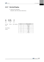
4. Parameters
4-42
4.2.7
Position Operation Setting Parameter
For detailed information, refer to "4.4.6 Position Operation Parameter Setting."
“**” Modification is not possible with the servo on & Power reset parameter.
“*” Parameter that cannot be modified with the servo on
Parameter
Unit
Initial
Details
Code
Name
Minimum
Maximum
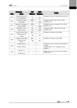
**P4-00
Position input pulse
logic
-
0
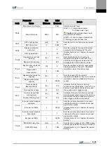
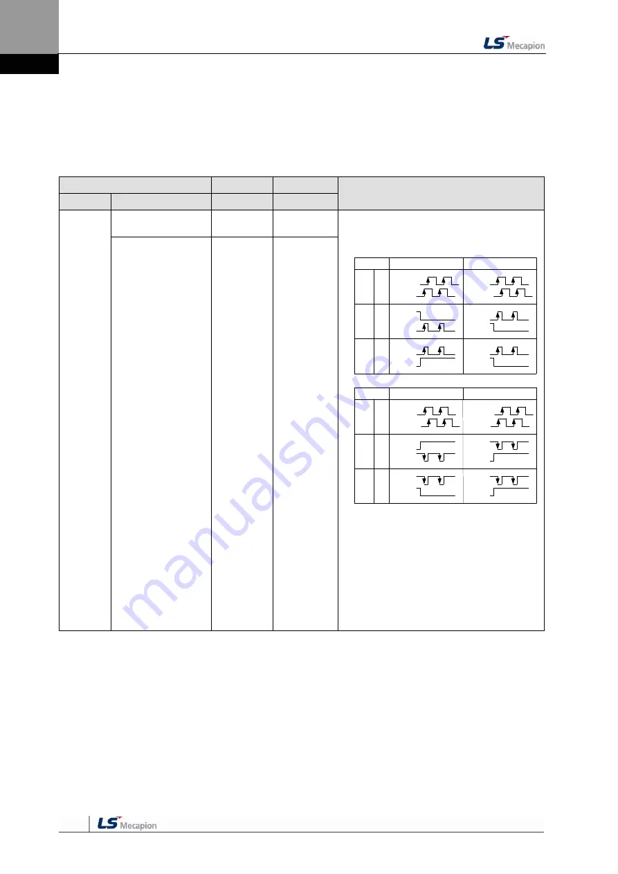
Sets logic for position operation input pulses.
- The type of position command input pulses
and rotation direction per logic are as follows:
PULS
(CN1-9)
SIGN
(CN1-11)
PULS
(CN1-9)
SIGN
(CN1-11)
0
1
Phase
A + B
Positive
Logic
CW+CCW
Positive
Logic
PULS
(CN1-9)
SIGN
(CN1-11)
2
Pulse +
direction
positive
logic
Forward rotation
Reverse rotation
PULS
(CN1-9)
SIGN
(CN1-11)
PULS
(CN1-9)
SIGN
(CN1-11)
PULS
(CN1-9)
SIGN
(CN1-11)
PF + PR
L Level
L Level
L Level
H Level
PULS
(CN1-9)
SIGN
(CN1-11)
PULS
(CN1-9)
SIGN
(CN1-11)
3
4
PULS
(CN1-9)
SIGN
(CN1-11)
5
Forward rotation
Phase
A + B
Negative
Logic
CW+CCW
Negative
Logic
Pulse +
direction
negative
logic
Reverse rotation
PULS
(CN1-9)
SIGN
(CN1-11)
PULS
(CN1-9)
SIGN
(CN1-11)
PF + PR
PULS
(CN1-9)
SIGN
(CN1-11)
H Level
H Level
H Level
L Level
E.g.) Relation between direction signals and
rotation directions when the position pulse
input logic is set to 2.
When the direction signal is low: Reverse
rotation (CW/clockwise)
When the direction signal is high: Forward
rotation (CCW/counterclockwise)
(Details:
Refer to “4.4.6 Position Operation
Parameter
Setting.”)
Pulse Input Logic
0
5
Summary of Contents for L7 A001
Page 1: ...VER 1 5...
Page 2: ......
Page 32: ...1 Product Components and Signals 1 20...
Page 38: ...2 Installation 2 6...
Page 54: ......
Page 188: ...7 Product Specifications 7 26 L7 A020 L7 A035 Weight 2 5 kg cooling fan included...
Page 210: ...8 Maintenance and Inspection 8 14...
Page 211: ...9 Appendix 9 1 9 Appendix...
Page 218: ...9 Appendix 9 8...
Page 221: ......
Page 222: ......


