3. Wiring Method
3-6
3.3.2
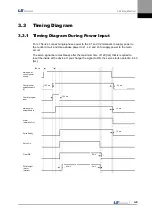
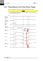
Timing Diagram at the Time of Alarm Trigger
When the alarm triggers in the servo drive, PWM is blocked and the motor stops.
Caution
Never reset the alarm before you solve the problem that triggered the alarm and change the
command signal (Servo ON) to OFF.
200 ms
Control power
establishment
5 [V]
Control
program
Reset
Main power
establishment
Alarm
(Normally On)
Servo RDY
Servo On
Clear DB
PWM
(Motor rotation)
RESET
150 ms
40 ms
10 ms
5 ms
2 ms
30 ms
Alarm triggered by
anomaly
Remove
causes that
triggered
alarm
Main power,
control power
supply
Summary of Contents for L7 A001
Page 1: ...VER 1 5...
Page 2: ......
Page 32: ...1 Product Components and Signals 1 20...
Page 38: ...2 Installation 2 6...
Page 54: ......
Page 188: ...7 Product Specifications 7 26 L7 A020 L7 A035 Weight 2 5 kg cooling fan included...
Page 210: ...8 Maintenance and Inspection 8 14...
Page 211: ...9 Appendix 9 1 9 Appendix...
Page 218: ...9 Appendix 9 8...
Page 221: ......
Page 222: ......

