4. Parameters
4-10
4.1.5
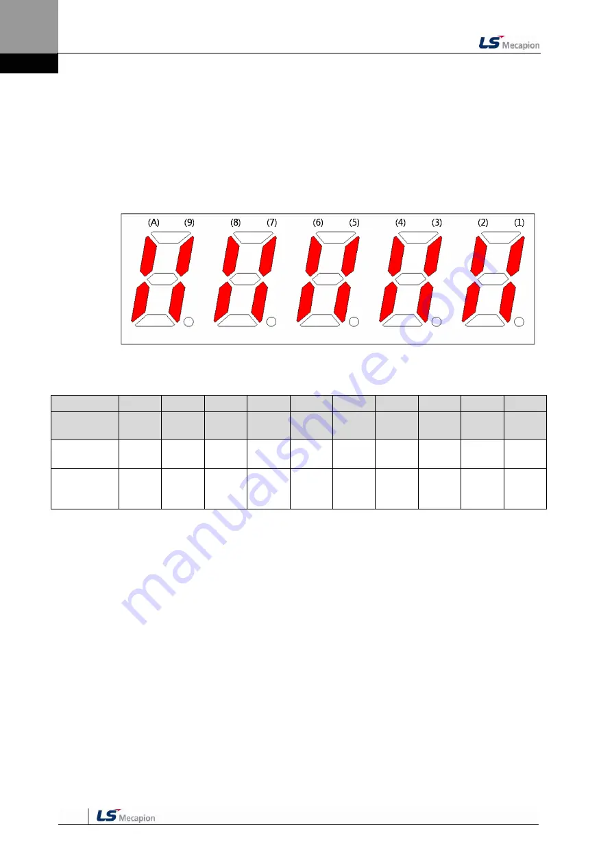
External Input Contact Signal Display [St-14]
You can check whether the ON/OFF status of digital input/output signals that access the
servo drive are on or off.
(1)
External Input Signal Display
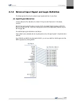
The positions of the seven segment LEDs and CN1 connector pins correspond as follows.
If an LED that corresponds to a pin is turned on/off, it indicates ON/OFF accordingly.
Input Contact Display
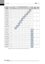
Number
(A)
(9)
(8)
(7)
(6)
(5)
(4)
(3)
(2)
(1)
Contact
Number
DIA
DI9
DI8
DI7
DI6
DI5
DI4
DI3
DI2
DI1
CN1
Pin number
48
18
19
20
46
17
21
22
23
47
Allocated
default
Signal name
STOP
EMG
CWLIM
CCWLI
M
DIR
ALMR
ST
SPD3
SPD2
SPD1
SVON
Summary of Contents for L7 A001
Page 1: ...VER 1 5...
Page 2: ......
Page 32: ...1 Product Components and Signals 1 20...
Page 38: ...2 Installation 2 6...
Page 54: ......
Page 188: ...7 Product Specifications 7 26 L7 A020 L7 A035 Weight 2 5 kg cooling fan included...
Page 210: ...8 Maintenance and Inspection 8 14...
Page 211: ...9 Appendix 9 1 9 Appendix...
Page 218: ...9 Appendix 9 8...
Page 221: ......
Page 222: ......

