4 - 20
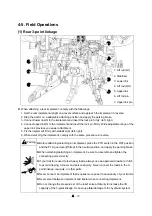
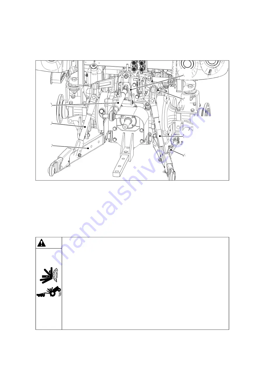
1. Lift rod (LH)
2. Stabilizer
3. Lower link
4. Lift rod (RH)
5. Upper link
6. Lift rod pin
7. Upper link pin
①
④
③
⑤
②
⑥
⑦
When attaching a rear implement, comply with the followings.
1. Set the rear implement upright on a level surface and approach the implement in reverse.
2. Stop the tractor on a adaptable attaching position and apply the parking brake.
3. Connect lower link(3) to the implement and insert the lock pin firmly. (left, right)
4. Connect upper link(5) to the implement and insert the lock pin firmly. Wide adjustable range of the
upper link provides you easier attachment.
5. Fix the implement firmly with stabilizer(2).(left, right).
6. When detaching the implement, comply with the same procedure in reverse.
(1) Rear 3-point linkage
4-5. Field Operations
Warning
▶
Before attaching/detaching an implement, place the PTO switch in the OFF position
and the PTO gear lever(if fitted) in the neutral position, and apply the parking brake.
▶
When attaching/detaching an implement, be sure to assemble and tighten the
connecting parts correctly.
▶
If your tractor is used to tow heavy loads, always use an approved drawbar or hitch
to avoid a tipping, turnover and personal injury. Never connect the loads to the 3-
point linkage, rear axle, or other parts.
▶
Never connect an implement that requires more power than capacity of your tractor.
▶
Never stand between implement and tractor when connecting implement.
▶
Do not change the pressure set of the relief valve arbitrarily to increase the lift
capacity of the 3-point linkage. It can cause fatal damage to the hydraulic system.
Summary of Contents for MT342
Page 1: ...LS TRACTOR OPERATOR S MANUAL MT342 MT347 MT352 MT357 Stage...
Page 2: ......
Page 46: ...1 32 2 9 6 11 3 1 Roll Bar 5 10 7 8 4 12 13 14 16 18 17 10...
Page 62: ...1 48...
Page 76: ...2 14...
Page 180: ...4 42...
Page 248: ...5 68...
Page 258: ...7 2 Unit mm Roll bar type Front tires 9 5 16 6PR Rear tires 13 6 24 8PR...
Page 263: ......
Page 264: ...P NO 52132436 05 DATE 20220000...

