5 - 28
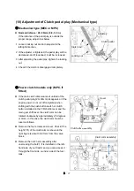
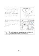
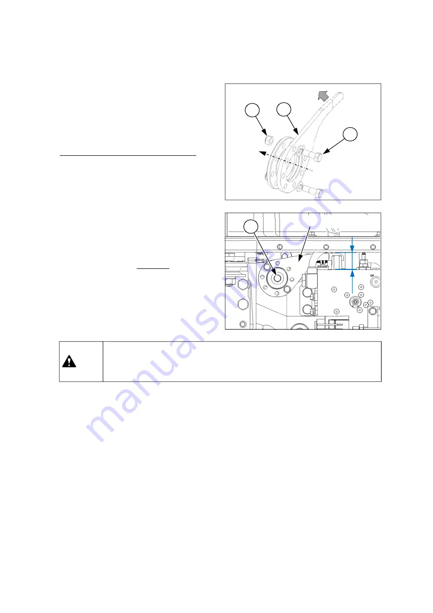
Unscrew the two bolts
④
and rotate the clutch
arm
③
counter-clockwise by 2.5 degrees.
Assemble the two bolts
④
with washers and nuts
⑤
into the next assembly holes counter-
clockwise from the previous attached holes.
Tighten the two bolts.
Tightening torque: 34~39 N.m (25~29 lb-ft)
Note: This rule must be adapted when you
adjust the clutch arm next times.
3
4
5
Clutch arm assembly
2
“H”
▶
If the clutch arm assembly is not adjusted on time, it may cause a rapid/earlier
clutch disk abrasion and damage of the synchro-mech gears.
Caution
Assemble the clutch arm assembly to the tractor
in the reverse order of disassembly, and tighten
the bolt
②
.
Check if the height(“H”) of the clutch arm from
the valve block is about 35~36mm after
adjustment.
New assembly hole
Counter-clockwise
Summary of Contents for MT342
Page 1: ...LS TRACTOR OPERATOR S MANUAL MT342 MT347 MT352 MT357 Stage...
Page 2: ......
Page 46: ...1 32 2 9 6 11 3 1 Roll Bar 5 10 7 8 4 12 13 14 16 18 17 10...
Page 62: ...1 48...
Page 76: ...2 14...
Page 180: ...4 42...
Page 248: ...5 68...
Page 258: ...7 2 Unit mm Roll bar type Front tires 9 5 16 6PR Rear tires 13 6 24 8PR...
Page 263: ......
Page 264: ...P NO 52132436 05 DATE 20220000...

