LSI LASTEM E-Log – User’s manual
21
x: value of the single actuation output: 0 = output is inactive, 1 = output is active.
yyy.y value of the power supply-voltage measured by the instrument (Volt);
^ indicates the selected actuator;
zzz
percentage value of power battery of the instrument. When the datalogger is
externally powered displays a value below 100% (60% typically) even when the battery is
fully charged (can be determined by switching off the charging LED on the frontal panel);
removing the external power supply the value of battery is shown correctly. This feature is
similar when “battery voltage” is a sampling measure
For diagnostic uses, use the keys
to shift on the selected actuator (indicated by ^
symbol) and key
to shift from switched on to switched off modes and viceversa .
From 2.13.01 firmware version it is possible to force the actuator state among to the internal logics
that could change (actuators logics or sensor power supply logics); in addition to the 0 value
(actuator off) and 1 value (actuator on) is shown the F letter, one for each actuator, if the forcing is
active.
In practice, if the forcing is also imposed to an actuator state (that can assume 0 or 1 value) means
that actuator will never be change by any internal logic (except the commands received from remote
through CISS communication protocol or Modbus that have priority on F status); if the F forcing is
off, the internal logic can normally change the actuator status.
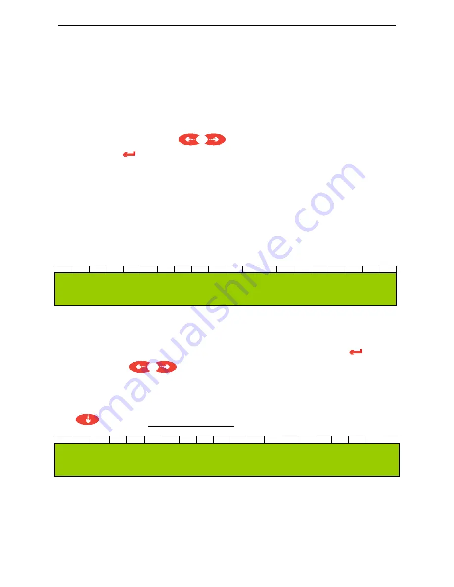
The diagnostic window is so displayed:
0
1
2
3
4
5
6
7
8
9
10
11
12
13
14
15
16
17
18
19
f
f
f
f
f
f
f
x
x
x
x
x
x
x
O
u
t
1
2
3
4
5
6
7
P
w
r
y
y
y
.
y
V
(
z
z
z
%
)
where:
^ indicates the selected actuator; it is displayed on the
Out
line instead of the actuator
number;
f indicates the forced/fixed state of the actuator; it is activated pressing the
button;
use the keys
to shift on the selected actuator; it can be assume the F value if
the forcing is active or it isn’t displayed if the actuator follows the programmed actuation
logics.
Key
to shift to the diagnostic window type 5:
where:
mm:ss remainig time for the next programmed connection (minutes:seconds)
cc:
GSM signal quality (measurement scale starting from 0 “no signal” up to 31
“maximim signal level”);
n:
number of successful connections done (starting from the previous statistical
reset);
0
1
2
3
4
5
6
7
8
9
10
11
12
13
14
15
16
17
18
19
G
P
R
S
N
T
:
m
m
:
s
s
C
S
Q
:
c
c
C
n
:
n
/
t
E
r
r
:
e
e
Summary of Contents for E-Log
Page 1: ...Cod INSTUM_00351_en E Log User s manual Updated on 09 18 2017...
Page 15: ...LSI LASTEM E Log User s manual 15...
Page 60: ...LSI LASTEM E Log User s manual 60 6 6 Mask of terminal board...
Page 61: ...LSI LASTEM E Log User s manual 61 6 7 Connection cables...
Page 62: ...LSI LASTEM E Log User s manual 62 6 8 Declaration of Conformity...


