background image


Sphensor 

 User manual 


LSI LASTEM SRL 

INSTUM_04291 

Pag. 10 / 32 


3


Configuration and identification 

At the factory exit, all Sphensor line devices use a default configuration:  they communicate on the same 
radio network (

Channel 

= 17, 

PanId 

= 0xDEFA, 

Key 

= 0x751751. 

NetworkId 

= 0xDEFA0170) and the sensors 

transmit the measurement data to Sphensor Gateway every 3 minutes.  Typically, in basic installations, where 
the system consists of a single Sphensor Gateway and some sensors, the default configurations are suitable 
for the proper functioning of the system. In more complex installations, consisting of multiple Sphensor Ga-
teways and different sensors and repeaters, it is necessary to change the configurations. 

Sphensor Manager

 is the software for configuring Sphensor equipment and verifying data reception. 

Before proceeding to the modification of the configurations it is desirable to have in mind already how to 
realize the network of sensors Sphensor. To facilitate the implementation and to increase the reliability of 
the connections it is recommended to subdivide the network into sub-networks (

Errore. L'origine riferimento 

non è stata trovata.

 shows an example),  where each sub-network has the following characteristics: 


A Sphensor Gateway 


Sensors located near the Sphensor Gateway 


Auxiliary repeaters or sensors, if any, with repetition function 


Same radio network for Sphensor Gateway, sensors and any repeaters and/or sensors with repetition 
function 


Once the configuration of each individual apparatus has been completed, it is recommended to identify it so 
that it can be easily found. For this purpose it is supplied with a writable cable tie-cord. 

You can, however, identify a sensor or repeater via software, via the 

Find me

 function of the 

Utilities

 menu 

of 

Sphensor Manager


3.1


Installing the Sphensor Manager software 

The Sphensor Manager software is located on the 

MW6501 USB flash drive - LSI LASTEM products.

  Alterna-

tively it can be downloaded from the website 

www.lsi-lastem.com

.  Run the Setup program for installation. 

To start the program, from the Windows Start menu choose LSI-Lastem, then 

SphensorManager


3.2


Sensor configuration 

The sensors are configured via the Sphensor Manager software, accessing the sensor via Sphensor Gateway. 
Proceed as follows: 

1.


Start Sphensor Manager. 

2.


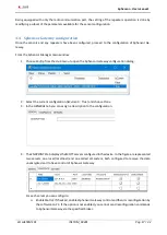
Turn on Sphensor Gateway and wait for the program to recognize it (in the example are shown the 
information related to the recognized Sphensor Gateway). 

Summary of Contents for Sphensor PRMPA0401

Page 1: ...Environmental monitoring solutions User manual...

Page 2: ...Sphensor User manual LSI LASTEM SRL INSTUM_04291 Pag 2 32 Document Sphensor User manual Pages 32 Revisions list Issue Date Author Description of changes Origin 10 11 2020 Reschiotto Astori...

Page 3: ...fied without notice No part of this manual may be reproduced in any form or by any electronic or mechanical means for any use without LSI LASTEM s written permission LSI LASTEM reserves the right to i...

Page 4: ...on 18 4 Installation of Sphensor equipment 19 4 1 Guidelines for placement 19 4 2 Installation 19 4 3 Sensors installation 20 4 3 1 Via screw stud 20 4 3 2 On electric plate 20 4 3 3 Hung 21 4 3 4 Via...

Page 5: ...Sphensor User manual LSI LASTEM SRL INSTUM_04291 Pag 5 32 10 Disposal 32 11 Contacting LSI LASTEM 32...

Page 6: ...eaters to be used where the sensor radio signal does not reach Sphen sor Gateway due to obstacles or long distances between the devices In Errore L origine riferimento non stata trovata a typical exam...

Page 7: ...ved quantities Sphensor Gateway is equipped with the following innovative features Possibility of connection via Ethernet LAN and via accessory 3G 4G modem or Wi Fi Possibility of local and autonomous...

Page 8: ...ensor code Rechargeable battery Non rechargeable battery low power sensor External power supply PRMPA0401 PRMPA0402 PRMPA0403 PRMPA0404 PRMPA0405 PRMPA0421 PRMPA0422 PRMPA0423 PRMPA0424 PRMPA0441 PRMP...

Page 9: ...midity dust and extreme temperatures tend to deteriorate or damage the instrument In such environments it s recommended to install inside suitable containers Power the instrument appropriately Respect...

Page 10: ...o non stata trovata shows an example where each sub network has the following characteristics A Sphensor Gateway Sensors located near the Sphensor Gateway Auxiliary repeaters or sensors if any with re...

Page 11: ...ormation related to your IP address serial number and password so that you do not have to enter it at each access and do not wait for the program to detect the device press This will be added to the L...

Page 12: ...he date time of the last message received from Sphensor Gateway Model is the model of the sensor Stack defines the type of sensor operation ftd the sensor can also act as a radio repeater mtd the sens...

Page 13: ...e sensor configuration dia log logically divided by topic The INFO tab displays information about the new configuration In detail CONFIG ID is an identifier unmodifiable automatically assigned In case...

Page 14: ...urements in error set the INST VALUES TRANSMISSION OFFSET parameter to a value greater than 0 for example 2 seconds to postpone the transmission of INST VALUES TRANSMISSION OFFSET giving the sensor th...

Page 15: ...is switched on only for the time it takes to transmit the data then it turns off and the sensor switches to low power mode In this mode the sensor is not accessible from Sphensor Gateway If the sensor...

Page 16: ...to 5 and SMOOTHING is equal to 12 the sensor will transmit the value every 5 seconds corresponding to the sliding average of the last minute 15 Press SAVE to save the configuration The sensor configur...

Page 17: ...Gateway configuration dialog 2 Select the current configuration IsCurrent True and choose Clone 3 In the GENERAL tab you can assign a description to the configuration 4 The ENDPOINTS tab displays the...

Page 18: ...stalling all Sphensor equipment it is recommended to check its correct functioning If the network has been subdivided into sub areas it is advisable to proceed by sub area Place the Sphensor apparatus...

Page 19: ...operation offer a high flexibility of placement not needing cables for power supply Install Sphensor repeaters if the distance between sensors and Sphensor Gateway is excessive or in the pre sence of...

Page 20: ...rifies the reception of data from all sensors taking into account the pro grammed transmission rate 4 3 Sensors installation Sphensor line sensors offer different types of installation resting on a sh...

Page 21: ...desk or a table The weight of the component allows unlimited tilt of the sensor without compromising its stability The rubber ring below prevents sliding on particularly smooth surfaces and protects a...

Page 22: ...Sphensor User manual LSI LASTEM SRL INSTUM_04291 Pag 22 32...

Page 23: ...e sensors may not be synchronised for a certain period of time espe cially after they are switched on In this condition which is assumed to persist for a limited time the sensor is not able to perform...

Page 24: ...f condition o No radio connectivity one flash o Connectivity present being networked two flashes System operating status alerts three slow flashes followed by one or more short flashes depending on th...

Page 25: ...sensor plane 1 additional measure on the normal of the same plane Measuring range 0 1 90 klx Resolution 0 01 lx Accuracy 2 lux 40 5 lux 40 Response to cosine 2 by angle of incidence 50 Radiation UV A...

Page 26: ...ion rate Settable On the basis of the sampling rate or only on the basis of mi nimum variation in the measured size Data recording Local Automatic in absence of radio connectivity linear storage until...

Page 27: ...on level 25 dB Noise emission level drift 0 5 dB CO2 Measuring range 0 5000 ppm t63 response time 140 s with the measured average 75 s with no average Accuracy 50 ppm 3 of the measured value Typical t...

Page 28: ...holder and with the other hand pull out the battery di scharge taking it to the sides in the central position during the operation avoid touching the electronic components welded on the board 4 Inser...

Page 29: ...e sensor serial that is the generator or recipient of the message action the rest of the MQTT topic represents the action taken by the target or sent to it 9 1 Instanteous data snapshots One of the mo...

Page 30: ...value of this field should not be considered The following table summarizes the sensor_type channel_index pairs that can be received from the sensor sensor_type channel_index name sht3x 0 Air temperat...

Page 31: ...hild device 9 3 Status snapshots To get the status of the sensor use the topic sphensor seriale_border_router seriale_sensore status Here is an example of a message received link_quality_in 3 rssi 67...

Page 32: ...ty of the production sale and disposal chain of the product ensuring the rights of the user Improper disposal of this product will result in law penalties 11 Contacting LSI LASTEM LSI LASTEM offers it...

Reviews: