RCI-1502 HRT Tele Boom Manual
4. Installation
SETTING UP THE CRANE
Lower the crane boom to a safe and convenient position.
INSTALLING BOOM PARTS
Recoil
Drum
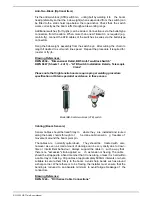
The recoil drum contains both the
angle sensor a nd length sensor for
telescopic cranes. The payout cable of the drum is also used for wiring the ATB
switch/es if required. It is supplied
for right hand side mounting
unless
ordered specifically for left hand side mounting.
The recoil drum comes complete with mounting bolts, payout wire roller guides
and boom tip tie-off bracket.
First remove the recoil drum cover a nd set aside. Fix the recoil drum and
payout cable to the right hand sid e of the main boom by welding the mounting
bolts provided to a suitable location on the side of the boom. Mount the recoil
drum on the bolts ensu ring that the el ectrical connection socket is pointing
towards the cabin. Ensure the recoil drum is mounted 'squarely' to the boom
side panel, this is essential to avoid incorrect payout wire spooling problems.
When the recoil drum is m ounted to the left hand side of the boom , the
electronic angle sensor must also be adjusted to get it working to its full range.
Please refer to drawings DWG 1199 , 1239, & 2159 at the rear of this m anual
for the correct position of the angle sensor.
Select a convenient uninterrupted payout cable alignment along the side of the
boom and cut and weld the anch or post provided to a suita ble position on the
boom head, so that the cable can be clamped into the groove on the post to
obtain a temporary line. Select positions for the intermediate cable roller guides
provided, one for each telescoping section and one or more for the main boom
allowing 3-4m between the drum and the nearest cable roller guide. Measure
the distance f rom the cable to the sides of the boom sections, record lengths
and mark the positions for the roller guides. Cut and weld the brackets of the
guides to the sides of the boom sections after remov ing the cable. Refit the
cable through the guides and then anchor it to the p
ost using the clamp
provided.
When the installation is complete, the recoil spring should be 'maximised' to
ensure that maximum available tension is applied to the payout wire to prevent
poor spooling onto the recoil drum. If possible, extend the boom fully at zero
degrees and pull the recoil drum payout wire fully out by hand until the spring
'locks up'. Allow 2 metres of payout wire to return back onto the drum and cut
off the exce ss. Remake the connection to the boom tip tie -off bracket.
Remember to leave sufficient cable l ength for connection to the anti-2-block
switch if one is being fitted.
If it is not possible to safely extend the boom at zero degrees, then simulate by
extending the payout by hand to a mark on the ground representing the full
telescopic extension.
Summary of Contents for RCI-1502 HRT
Page 2: ......
Page 4: ......
Page 6: ......
Page 8: ......
Page 14: ......
Page 22: ......
Page 44: ......
Page 52: ......
Page 56: ......
Page 58: ......
Page 59: ...Appendix 8 1 Data Logging on RCI Systems ...
Page 60: ......
Page 66: ...Data Logging on RCI Systems Example Lift Cycles ...
Page 71: ...Appendix 8 2 Drawings ...
Page 72: ......
Page 73: ......
Page 74: ......
Page 76: ......
Page 77: ...APPROVED BY TOL 0 0 0 1 2 3 4 55 26 2 0 7 2 8 9 1 1 1 1 0 7 5 6 2 ...
Page 79: ...APPROVED BY TOL 0 0 0 1 22 3 4 5 6 0 22 2 1 7 8 98 1 7 8 98 7 8 98 7 8 98 1 0 9 8 3 6 8 3 ...
Page 80: ... APPROVED BY 0 1 2 22 3 3 3 TOL 4 4 23 4 232 22 3 242 4 2 32 2 3516 7 8 7 7 9 2 3 42 4 2 ...
Page 81: ... APPROVED BY 0 1 2 22 3 3 3 TOL 4 4 23 4 232 22 5 0 42 4 2 3617 8 9 8 8 2 ...
Page 82: ......
Page 83: ......
Page 87: ......
Page 88: ......
Page 89: ......
Page 90: ......
Page 91: ......
Page 92: ......
Page 93: ......
Page 94: ......
Page 95: ......
Page 96: ......
Page 97: ......
Page 98: ......
Page 99: ......
Page 100: ......
Page 101: ......
Page 103: ......
Page 104: ......
Page 105: ......
Page 106: ......
Page 107: ......
Page 108: ......
Page 109: ......


