RCI-1502 HRT Tele Boom Manual
Connectors
It is recommended that the installer applies a suitable silicone grease (e.g.,
Dow Corning 4 “Electrical Insulating Comp ound” or any similar compound) on
the plugs and sockets prior to connec ting the cab les. The silicone grease
should be smeared across the connecto r contact points to increase the wa ter
proofing of the connector.
INSTALLING CABIN PARTS
Display Unit and Key Switch Box
Fit the RCI-1502 Display Unit a nd Key S witch Box in a convenient position in
the crane cabin such that the operator can view the display s and reach the
push buttons comfortably.
Connect the Switch Box power supply lead to the key start switch or directly to
the battery via a relay that is energised by the key start switch. Ensure that the
polarity of the power supply is correctly connected.
Standard back plate bracket and kit comprising of bolts and nuts are provided.
Special bracket may need to be fabricated on site for suitable mounting in the
cabin.
Connect the load, angle, and anti-two-block ATB cables to the display unit.
Note: If a good earth connection between the mounting bracket and the
cabin cannot be guaranteed then the earthing wire attached to the base of
the display must be used to properly earth the display. Failure to do so
could result in a non-operational ATB signal and faults due to Radio
Frequency Interference.
Drawing References:
DWG 0279 – “Dimensional Drawing, RCI-1502 Display”
DWG 2459 – “Dimensional Detail, RCI-1502 Switchbox”
DWG 3336 – “RCI-1502 Switchbox V2 Wiring Diagram”
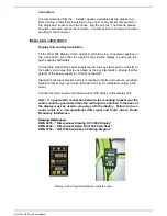
Display unit and typical installation inside the cabin
Summary of Contents for RCI-1502 HRT
Page 2: ......
Page 4: ......
Page 6: ......
Page 8: ......
Page 14: ......
Page 22: ......
Page 44: ......
Page 52: ......
Page 56: ......
Page 58: ......
Page 59: ...Appendix 8 1 Data Logging on RCI Systems ...
Page 60: ......
Page 66: ...Data Logging on RCI Systems Example Lift Cycles ...
Page 71: ...Appendix 8 2 Drawings ...
Page 72: ......
Page 73: ......
Page 74: ......
Page 76: ......
Page 77: ...APPROVED BY TOL 0 0 0 1 2 3 4 55 26 2 0 7 2 8 9 1 1 1 1 0 7 5 6 2 ...
Page 79: ...APPROVED BY TOL 0 0 0 1 22 3 4 5 6 0 22 2 1 7 8 98 1 7 8 98 7 8 98 7 8 98 1 0 9 8 3 6 8 3 ...
Page 80: ... APPROVED BY 0 1 2 22 3 3 3 TOL 4 4 23 4 232 22 3 242 4 2 32 2 3516 7 8 7 7 9 2 3 42 4 2 ...
Page 81: ... APPROVED BY 0 1 2 22 3 3 3 TOL 4 4 23 4 232 22 5 0 42 4 2 3617 8 9 8 8 2 ...
Page 82: ......
Page 83: ......
Page 87: ......
Page 88: ......
Page 89: ......
Page 90: ......
Page 91: ......
Page 92: ......
Page 93: ......
Page 94: ......
Page 95: ......
Page 96: ......
Page 97: ......
Page 98: ......
Page 99: ......
Page 100: ......
Page 101: ......
Page 103: ......
Page 104: ......
Page 105: ......
Page 106: ......
Page 107: ......
Page 108: ......
Page 109: ......


