RCI-1502 HRT Tele Boom Manual
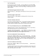
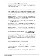
5.2.4. Calibrate Heavy Main Load (F-03)
Please see Section 5.5.2. “Calibrating Heavy Main Load” for details.
5.2.5. View Calibrated Aux Load (F-04) – For Twin Winch Cranes Only
The calibrated Aux Winch load can be verified on normal operating mode (operator’s
screen). This function is used to view the aux calibrated load while still in calibration
mode. This is useful when just verifying accuracy of the load
readout and the
calibration has not yet been finalised.
5.2.6. Calibrate Light Aux Load (F-05) – For Twin Winch Cranes Only
Please see Section 5.6.1. “Calibrating Light Aux Load” for details.
5.2.7. Calibrate Heavy Aux Load (F-06) – For Twin Winch Cranes Only
Please see Section 5.6.2. “Calibrating Heavy Aux Load” for details.
5.2.8. View Uncalibrated Angle Input (F-07)
Use this function to view the raw counts (or raw data) of the angle sensor. Please also
Section 5.1. “Verifying Operation of Sensors” for details.
5.2.9. View Calibrated Angle Input (F-08)
The calibra ted angle can be verified on norma l operating mode (operator’s screen ).
This function is used to view the calibrated angle (in degrees) while still in calibration
mode. This is useful when just v erifying accuracy of the angle readout and the
calibration has not yet been finalised.
5.2.10. Calibrate Low Angle (F-09)
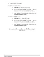
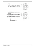
Please see Section 5.3.1. “Calibrating Low Boom Angle” for details.
5.2.11. Calibrate High Angle (F-10)
Please see Section 5.3.2. “Calibrating High Boom Angle” for details.
5.2.12. View Uncalibrated Boom Length Input (F-11)
Use this function to view the raw counts (or raw data) of the length sensor. Please also
Section 5.1. “Verifying Operation of Sensors” for details.
Summary of Contents for RCI-1502 HRT
Page 2: ......
Page 4: ......
Page 6: ......
Page 8: ......
Page 14: ......
Page 22: ......
Page 44: ......
Page 52: ......
Page 56: ......
Page 58: ......
Page 59: ...Appendix 8 1 Data Logging on RCI Systems ...
Page 60: ......
Page 66: ...Data Logging on RCI Systems Example Lift Cycles ...
Page 71: ...Appendix 8 2 Drawings ...
Page 72: ......
Page 73: ......
Page 74: ......
Page 76: ......
Page 77: ...APPROVED BY TOL 0 0 0 1 2 3 4 55 26 2 0 7 2 8 9 1 1 1 1 0 7 5 6 2 ...
Page 79: ...APPROVED BY TOL 0 0 0 1 22 3 4 5 6 0 22 2 1 7 8 98 1 7 8 98 7 8 98 7 8 98 1 0 9 8 3 6 8 3 ...
Page 80: ... APPROVED BY 0 1 2 22 3 3 3 TOL 4 4 23 4 232 22 3 242 4 2 32 2 3516 7 8 7 7 9 2 3 42 4 2 ...
Page 81: ... APPROVED BY 0 1 2 22 3 3 3 TOL 4 4 23 4 232 22 5 0 42 4 2 3617 8 9 8 8 2 ...
Page 82: ......
Page 83: ......
Page 87: ......
Page 88: ......
Page 89: ......
Page 90: ......
Page 91: ......
Page 92: ......
Page 93: ......
Page 94: ......
Page 95: ......
Page 96: ......
Page 97: ......
Page 98: ......
Page 99: ......
Page 100: ......
Page 101: ......
Page 103: ......
Page 104: ......
Page 105: ......
Page 106: ......
Page 107: ......
Page 108: ......
Page 109: ......


