Sync/EF Reinsertion Unit
2-17
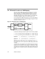
The hexidecimal address sequence of the read (underlined) and write
pointers is:
00, 01, 03, 02, 06, 07, 05, 04, 0C, 0D, 0F, 0E, 0A, 0B, 09, 08,
18, 19, 1B, 1A, 1E, 1F, 1D, 1C, 14, 15, 17, 16, 12, 13, 11, 10,
30, 31, 33, 32, 36, 37, 35, 34, 3C, 3D, 3F, 3E, 3A, 3B, 39, 38,
28, 29, 2B, 2A, 2E, 2F, 2D, 2C, 24, 25, 27, 26, 22, 23, 21, 20,
60, 61, 63, 62, 66, 67, 65, 64, 6C, 6D, 6F, 6E, 6A, 6B, 69, 68,
78, 79, 7B, 7A, 7E, 7F, 7D, 7C, 74, 75, 77, 76, 72, 73, 71, 70,
50, 51, 53, 52, 56, 57, 55, 54, 5C, 5D, 5F, 5E, 5A, 5B, 59, 58,
48, 49, 4B, 4A, 4E, 4F, 4D, 4C, 44, 45, 47, 46, 42, 43, 41, 40.
The L64777 download through the microprocessor interface starts with
the beginning read pointer value. The write pointer start value is always
fixed to zero. Every time the L64777 accesses the FIFO delay value in
the microprocessor interface (FDEL, see Section 4.1.3, “Register 2,”
page 4-5), the pointers are reset to the these values. If the L64777 is
programmed to the FIFO Autoreset mode (see Section 4.1.7,
“Register 6,” page 4-7), it forces the pointers to the value in the FDEL
register on the read side and to zero on the write side after every FIFO
collision.
Attention:
The only legal load values for the read pointer are Gray
Code numbers with even parity, which means an even
number of 1s (underlined in the above table). Therefore, the
FIFO delay increment can only be in steps of two. The
device achieves maximum delay with a value of 0x41; the
optimum (center) distance to overrun and underruns is
0x60.
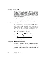
2.6 Sync/EF Reinsertion Unit
The following subsections describe the Sync/EF modes, error flag
insertion, and scrambler.
Summary of Contents for L64777
Page 1: ...L64777 DVB QAM Modulator Order Number I14031 A Technical Manual June 2000...
Page 10: ...x Contents...
Page 14: ...1 4 Introduction...
Page 90: ...5 10 Signals...
Page 110: ...A 8 Programming the L64777 in Serial Host Interface Mode...
Page 116: ...C 2 Monitoring Device Internal Signals...
Page 124: ......


