Learning Advanced Features
244
Grou
p
Code
Name
LCD Display
Parameter Setting
Setting
Range
Unit
IN
65
–
71
Px terminal
configuration
Px Define(Px: P1
–
P7)
28
2nd Motor 0-55
-
2
nd
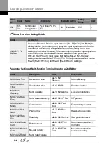
Motor Operation Setting Details
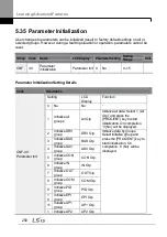
Code
Description
IN-65
–71 Px
Define
Set one of the multi-function input terminals (P1
–P5) to 26 (2nd Motor) to
display the M2 (2nd motor group) group. An input signal to a multi-function
terminal set to 2nd motor will operate the motor according to the code
settings listed below. However, if the inverter is in operation, input signals to
the multi-function terminals will not read as a 2nd motor parameter.
PRT-50 (Stall Prevent) must be set first, before M2-28 (M2-Stall Lev)
settings can be used. Also, PRT-40 (ETH Trip Sel) must be set first, before
M2-29 (M2-ETH 1 min) and M2-30 (M2-ETH Cont) settings.
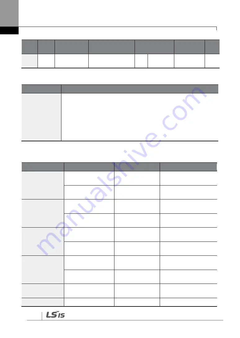
Parameter Setting at Multi-function Terminal Input on a 2nd Motor
Code
Description
Code
Description
M2-04 Acc Time
Acceleration time
M2-15 M2-
Efficiency
Motor efficiency
M2-05 M2-Dec
Time
Deceleration time
M2-17 M2-Rs
Stator resistance
M2-06 M2-
Capacity
Motor capacity
M2-18 M2-Lsigma
Leakage inductance
M2-07 M2-Base
Freq
Motor base frequency M2-25 M2-V/F Patt
V/F pattern
M2-08 M2-Ctrl
Mode
Control mode
M2-26 M2-Fwd
Boost
Forward torque boost
M2-10 M2-Pole
Num
Pole number
M2-27 M2-Rev
Boost
Reverse torque boost
M2-11 M2-Rate
Slip
Rated slip
M2-28 M2-Stall Lev Stall prevention level
M2-12 M2-Rated
Curr
Rated current
M2-29 M2-ETH 1
min
Motor heat protection 1
min rating
M2-13 M2-Noload
Curr
No-load current
M2-30 M2-ETH
Cont
Motor heat protection
continuous rating
M2-14 M2-Rated
Motor rated voltage
Summary of Contents for H100
Page 14: ......
Page 18: ...Preparing the Installation 4 37 90 kW 3 Phase ...
Page 27: ...Preparing the Installation 13 ...
Page 47: ...33 Installing the Inverter ...
Page 48: ...Installing the Inverter 34 Input and Output Control Terminal Block Wiring Diagram ...
Page 61: ...47 Installing the Inverter ...
Page 71: ...Learning to Perform Basic Operations 57 ...
Page 88: ...Learning to Perform Basic Operations 74 ...
Page 103: ...89 Learning Basic Features Code Description V1 Quantizing ...
Page 129: ...115 Learning Basic Features ...
Page 140: ...Learning Basic Features 126 ...
Page 148: ...Learning Basic Features 134 ...
Page 171: ...157 Learning Advanced Features Deceleration dwell operation ...
Page 183: ...169 Learning Advanced Features ...
Page 184: ...Learning Advanced Features 170 PID Command Block ...
Page 185: ...171 Learning Advanced Features PID Feedback Block ...
Page 186: ...Learning Advanced Features 172 PID Output Block ...
Page 187: ...173 Learning Advanced Features PID Output Mode Block ...
Page 197: ...183 Learning Advanced Features ...
Page 201: ...187 Learning Advanced Features Code Description 100 EPID1 Control block ...
Page 202: ...Learning Advanced Features 188 EPID2 Control block ...
Page 237: ...223 Learning Advanced Features Time Period Schedule AP3 38 Except3 Day 01 01 ...
Page 244: ...Learning Advanced Features 230 ...
Page 259: ...245 Learning Advanced Features Code Description Code Description Volt ...
Page 362: ...Learning Protection Features 348 ...
Page 415: ...401 RS 485 Communication Features Item Standards Parity check None ...
Page 524: ...Table of Functions 510 ...
Page 533: ...Table of Functions 519 ...
Page 547: ...533 Troubleshooting ...
Page 585: ...Technical Specification 571 ...
Page 594: ...580 ...
Page 595: ...581 ...
Page 596: ...582 ...

