588
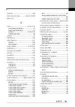
G
ground .................................................................................................. 26
class 3 ground ..................................................... 27
ground cable specifications ................................ 10
ground fault trip ............................... Refer to
Ground Trip
Ground Trip .................................................................................... 554
H
H100 expansion common area parameter ........... 403
control area parameter (Read/Write) .............. 414
memory control area parameter (Read/Write)
....................................................................... 418
monitor area parameter (read only) ................ 403
half duplex system ................................................................... 373
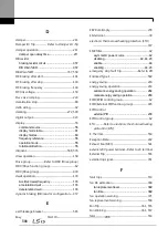
I
I/O point map.............................................................................. 434
I2 38
analog input selection switch (SW4) ................. 38
frequency setting(current/voltage) terminal ...... 38
I2 Terminal ...................................................................................... 101
IA (illegal data address) ........................................................ 392
ID (illegal data value) ............................................................. 393
IF (illegal function) .................................................................... 392
IN (Input terminal function group) .................... 62, 460
In Phase Open ............................................................................. 554
initializing accumulated electric energy count ... 287
input and output specifications ..................................... 577
input open-phase fault trip .............. Refer to
In Phase
Open
input phase open
input open-phase protection ............................ 350
input power frequency ......................................................... 277
input power voltage ............................................................... 278
input power voltage settings ........................................... 277
input terminal ..................................................................... 37, 156
A (NO) or B (NC) terminal configuration ......... 156
bit setting ............................................................ 156
CM terminal ..........................................................37
I2 terminal .............................................................38
NO/NC configuration ........................................ 156
P1
–P7 terminal ....................................................37
TI terminal ............................................................38
V1 terminal ...........................................................37
VR terminal ..........................................................37
input terminal contact
A contact ............................................................ 351
B contact............................................................ 351
Input terminal function group ...... Refer to IN (Input
terminal function group)
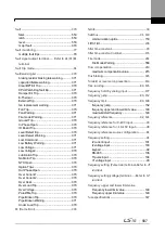
inspection
annual inspection .............................................. 569
bi-annual inspection ......................................... 572
daily inspection ................................................. 568
installation .......................................................................................... 14
basic configuration diagram
...........................16
installation flowchart ............................................14
location ................................................................... 6
mounting the Inverter ..........................................17
side-by-side installation ......................................... 8
wiring .....................................................................24
installation conditions .................................................................. 5
INV Over Load
Inv Over Load Warning .................................... 557
Inverter OLT ................................................................................... 554
inverter overload protection (IOLT) ............................. 352
Inverter overload warning .................................................. 371
IO Board connection fault trip ...... Refer to
IO
Board
Trip
IO Board Trip ................................................................................ 557
IP 20 .................................................................................................... 582
IP 20 Type external dimensions ..................................... 584
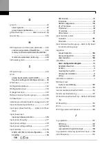
J
Jog operation ............................................................................... 167
FWD Jog ........................................................... 167
Jog frequency ................................................... 167
Jog operation 2 by terminal input .................... 168
Jog operation 2-Rev Jog by terminal input ......... 168
jump frequency .......................................................................... 152
Summary of Contents for H100
Page 14: ......
Page 18: ...Preparing the Installation 4 37 90 kW 3 Phase ...
Page 27: ...Preparing the Installation 13 ...
Page 47: ...33 Installing the Inverter ...
Page 48: ...Installing the Inverter 34 Input and Output Control Terminal Block Wiring Diagram ...
Page 61: ...47 Installing the Inverter ...
Page 71: ...Learning to Perform Basic Operations 57 ...
Page 88: ...Learning to Perform Basic Operations 74 ...
Page 103: ...89 Learning Basic Features Code Description V1 Quantizing ...
Page 129: ...115 Learning Basic Features ...
Page 140: ...Learning Basic Features 126 ...
Page 148: ...Learning Basic Features 134 ...
Page 171: ...157 Learning Advanced Features Deceleration dwell operation ...
Page 183: ...169 Learning Advanced Features ...
Page 184: ...Learning Advanced Features 170 PID Command Block ...
Page 185: ...171 Learning Advanced Features PID Feedback Block ...
Page 186: ...Learning Advanced Features 172 PID Output Block ...
Page 187: ...173 Learning Advanced Features PID Output Mode Block ...
Page 197: ...183 Learning Advanced Features ...
Page 201: ...187 Learning Advanced Features Code Description 100 EPID1 Control block ...
Page 202: ...Learning Advanced Features 188 EPID2 Control block ...
Page 237: ...223 Learning Advanced Features Time Period Schedule AP3 38 Except3 Day 01 01 ...
Page 244: ...Learning Advanced Features 230 ...
Page 259: ...245 Learning Advanced Features Code Description Code Description Volt ...
Page 362: ...Learning Protection Features 348 ...
Page 415: ...401 RS 485 Communication Features Item Standards Parity check None ...
Page 524: ...Table of Functions 510 ...
Page 533: ...Table of Functions 519 ...
Page 547: ...533 Troubleshooting ...
Page 585: ...Technical Specification 571 ...
Page 594: ...580 ...
Page 595: ...581 ...
Page 596: ...582 ...


