


SV-iS7 CANopen Manual
5
3. Diagnosis of the Option Statuses and LED Definition
3.1
Definition of the LED Signal
The CANopen communication option has 4 LEDs.
LED
Description
CPU
When the Option card is energized and the CPU is in normal operation state, this LED
is turned on and off at 1 second cycle – on for 500 ms and off for 500 ms.
ERR
This LED turns on if the Option parameters have been set up inappropriately, or the
Internal CAN communication between the inverter and the CANopen is lost.
NODE
This LED turns on according to the status of the current NMT (Network Management).
BUS
This LED turns on or off according to the baud rate or profile set up, or communication
status.
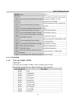
3.2
Diagnosis of Option by LED Signal
LED LED Signal
Option Status
Possible Cause
Action
CPU
Kept OFF
No Power
Failure in power supply
(5V) to the CANopen
communication card
Check inverter power supply.
Check power supply to the
CANopen communication card
Blink at 1 sec
intervals
On Power
5V power supplied
Normal status
ERR
Kept OFF
No Error
Normal Option setting
Normal status
Blinks
synchronously
with the CPU
LED
Internal CAN
communication
Error
Data communication
between the inverter and
Option is lost.
Turn the inverter power off,
reinstall the Option card and turn
the power on again.
Blinks
asynchronously
with the CPU
LED
FBus ID
Setting Error
‘0’ is entered as the ID of
the COM-7 FBus
Enter a figure between 1~127, not
zero, into the FBus ID, and
execute COM-94 Comm Update


