LSP16H, LSP21H, LSP24H, LSP28H Owner's Manual
6
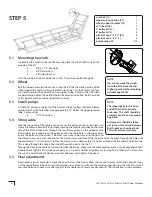
5.1 Mounting the winch.
In attaching the winch to the mainframe tube, place the winch shaft towards the
outside of the lift.
2 - 3/8" x 6 1/2" hex bolts
2 - 3/8" flat washers
2 - 3/8" nylon lock nut
with the washers and nuts inside the winch. These are in bolt package #6.
5.2 Wheel
Bolt the wheel extension tube to the winch shaft. Slide the white portion of the
wheel support bracket over the wheel extension tube. Turn the bracket until you
can slide it just past the end of the wheel support tube. Adjust so that the tubes
are parallel and tighten the bolt that holds the bracket in position. Bolt the wheel
to the wheel extension tube and tighten to secure.
5.3 Install pulleys
Install the 3" pulleys to the front of the h-unit and the 6" pulleys to the mainframe
upright tubes in the holes that are approximately 12" below the upper spreader
tube. Secure using:
4 - 1/2" flat washers
5.4 String cable
Take the loose end of the cable and run it over the pulley on the H-unit closest to
where the cable is attached. String it back through the mainframe pulley on the same
side of the lift and then over through the mainframe pulley on the opposite side.
String under the remaining H-unit pulley. Locate the cable hole in the winch drum
inside the bottom of the winch. The drum may have to be turned so the slot and
the clamp screws are accessible. Loosen the clamp screw and thread the straight end of the cable through the hole until
approximately 1" is sticking out. Tighten the clamp screws down with a 5/32 allen wrench until the cable is held securely.
This is done through the hole in the side of the winch next to the shaft.
Take up the slack in the cable by turning the wheel clockwise. Make sure the cable winds evenly as in the figure above right.
Double check that the lift is working properly as it is raised and that all pulleys are turning freely. After the first few times
the winch is used check the clamp screws for tightness and tighten if required.
5.5 Final adjustments
Now tighten all nuts and bolts, except the ones that must be free to allow the H-units to pivot. Install the 4 plastisol caps,
2 at the top of the mainframe and 2 on the cradle tubes. Move your lift into the water and position it so that the lift is level. If
your lake bottom is uneven, we offer Leg Kits that enable you to level your pontoon lift. The installation is now complete.
NOTE
Never over crank the winch.
Once the lift has reached its
highest point, further cranking
will damage the lift.
NOTE
The wheel needs to thread on
and off the shaft to activate
the brake. This shaft should be
greased yearly to ensure proper
operation.
Extreme care should be taken
not to cross thread and damage
the threads on the wheel hub.
This will void your warranty.
STEP 5
winch #5 [13]
1
wheel extension tube [27]
1
wheel support bracket [21]
1
32" wheel [26]
1
3" pulley kit [31]
2
6" pulley kit [3]
2
plastisol cap 2" x 2.5" [33]
2
plastisol cap 2" x 5" [1]
2
bolt package #5
1/1

