background image

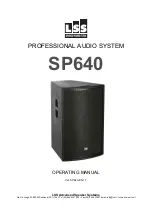
SP640_

________________________________________________________________________________ 

12| Operating Manual ver. SP640-EN-1.1


TROUBLESHOOTING 

Problem 

Possible cause (s) 

Action 

1. No Sound 

Amplifier 

Connect a known working test speaker to the amplifier outputs. If 
there is no sound, check that all the electronics are on, the signal 
routing  is  correct,  the  source  is  active,  the  volume  is  turned  up, 
and so on. Correct/repair/replace as necessary. If there is sound, 
the problem is in the wiring. 

Wiring 

Verify  that  you  have  connected  the  correct  wire  pairs  to  the 
amplifier.  Play  something  at  low  level  through  the  amplifier  (for 
example, from a CD player or tuner). Connect the test speaker in 
parallel  with the malfunctioning line.  If the sound level has gone 
or  is  very  weak,  the  line  has  a  short  in  it  (possibly  a  severe 
scrape,  pinch,  or  staple  puncture).  If  the  sound  level  is  normal, 
the  wire  is  open  (possibly  a  cut  wire  or  a  missed  connection). 
Using  the  test  speaker,  move  down  the  line  and  test  each 
connection/junction  until  you  find  the  problem  and  correct  it. 
Observe proper polarity. 

2. Poor Low 

Frequency 

Response 

Speakers wired out-

of-polarity 

When  two  speakers  are  connected  out  of  polarity,  the  low 
frequencies will cancel each other acoustically. Carefully observe 
the  wire  markings  or  tracers  on  your  speaker  wires.  Verify  that 
the  amplifier  (+)  terminal  is  connected  to  pin  1+  of  the  NL4 
connector and the amplifier (-) terminal is connected to pin 1- of 
the NL4 connector. 

3. Intermittent 

output such as 

crackling or 

distortion 

Faulty Connection 

Check  all  connections  at  amplifier  and  speakers  to  ensure  they 
are  all  clean  and  tight.  If  the  problem  persists,  it  may  be  in  the 
amplifier or wiring. See Problem 1 above. 

4. Constant 

noise such as 

buzzing, 

hissing, 

humming 

Defective amplifier or 

other electronic 

Devices 

If  the  noise  is  present  but  no  program  material  is  playing,  the 
likely cause is the signal chain in the electronics.  Evaluate each 
component as necessary to isolate the problem. 

Poor system 

grounding or ground 

loop 

Check and correct the system grounding, as required. 

If these suggestions do not solve your problem, contact your nearest LSS dealer or LSS distributor. 


Summary of Contents for SP640

Page 1: ...SSIONAL AUDIO SYSTEM SP640 OPERATING MANUAL Ver SP640 EN 1 1 LSS Advanced Speaker Systems Via On Longo 53 89024 Polistena RC ITALY Tel 39 966 9321299 Fax 39 966 933007 Email info lss it Internet www l...

Page 2: ...No part of this publication may be reproduced stored in a retrieval system or transmitted in any form or by any means mechanical electronic photocopying recording or otherwise without the prior writte...

Page 3: ...________________________ Operating Manual ver SP640 EN 1 1 3 SUMMARY INTRODUCTION 4 SAFETY AND WARNING 5 APPLICATION 6 PHYSICAL DESCRIPTION 6 TECHNICAL SPECIFICATIONS 7 INSTALLATION AND WIRING 8 WEEE...

Page 4: ...sional audio products the result of exceptional engineering and meticulous craftsmanship This manual is intended for use with LSS loudspeaker This includes safety precautions installation set up and o...

Page 5: ...ork even when the power switch is in position 0 OFF Before any maintenance disconnect the power cable from the outlet Risk of electric shock only for self powered system IMPORTANT SAFETY PRECAUTIONS R...

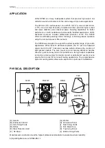
Page 6: ...0 was designed to support the widest possible range of pro audio applications While ideal for distributed systems the 13 per side trapezoid angles match the 90 horizontal coverage pattern allowing the...

Page 7: ...1 Watt 1 m Full Range Passive 98 dB LF 98 dB HF 103 dB Max SPL Calculated Power AES PEAK 125 dB 130 dB Nominal Input Impedance Full Range Passive 8 LF 8 HF 16 Power Handling Watt cont AES Full Range P...

Page 8: ...r using two M10 screwbolts If needed replace the screwbolts with eyebolts More detaliled One bracket is connected between top and left side of case One bracket is connected between top and right side...

Page 9: ...nel there are two Speakon NL4 connectors referred as IN and OUT IN is the input connector and must be connected to the amplifier OUT is a LINK OUT and can be connected to other systems In the sp640 bo...

Page 10: ...speakers is represented below You can now use the system NL4 Pin Configuration Pins 1 and 1 Used Pins 2 and 2 Not Used Amplifier Output A Output B Input A Input B Mixer Amplifier Load per Output Chann...

Page 11: ...es private households within the EU can give free electrical and electronic equipment to designated collection facilities In some countries your local retailer may withdraw the old product for free if...

Page 12: ...t each connection junction until you find the problem and correct it Observe proper polarity 2 Poor Low Frequency Response Speakers wired out of polarity When two speakers are connected out of polarit...

Page 13: ...______________________________________________________________________________ Operating Manual ver SP640 EN 1 1 13 DIMENSIONS FRONT TOP BOTTOM SIDE 23cm 52 4cm 70cm REAR 46 2cm...

Page 14: ...SP640_________________________________________________________________________________ 14 Operating Manual ver SP640 EN 1 1 NOTES...

Page 15: ...______________________________________ Operating Manual ver SP640 EN 1 1 15 CONTACT INFORMATION LSS Advanced Speaker Systems Via On Longo 53 89024 Polistena RC ITALY Tel 39 966 9321299 Fax 39 966 9330...

Reviews: