background image

Airmover Fan Installation Instructions 


10 | 

P a g e


AFTER INSTALLATION


WOBBLE: 

NOTE: ceiling fans tend to move during operation due to the fact that they are mounted on a rubber grommet. If the 

fan was mounted rigidly to the ceiling it would cause excessive vibration. Movement of a few centimetres is quite 

acceptable and DOES NOT suggest any problem.   

TO REDUCE THE FAN WOBBLE:

 Please check that all screws which fix the mounting bracket and down rod are 

secure.   

BALANCING KIT: 

A balancing kit is provided to balance the ceiling fan on initial installation. Please refer to the 

instruction on how to use the balancing kit.


The balancing kit can be used to assist re-balancing should the ceiling 

fan become un-balanced again. Store your balancing kit away after installation for future use if required.


NOISE: 

When it is quiet (especially at night) you may hear occasional small noises. Slight power fluctuations and frequency 

signals superimposed in the electricity for off-peak hot water control, may cause a change in fan motor noise. This 

is normal. Please allow a 24-

hour “settling-in” period, most noises associated with a new fan disappear during this 

time.   
The manufacturer’s warranty covers actual faults that may develop and NOT minor complaints such as hearing the 

motor run 

– All electric motors are audible to some extent. 


CARE AND CLEANING: 


Periodic cleaning of your ceiling fan is the only maintenance required. Use a soft brush or lint free cloth to avoid 

scratching the paint finish. Please turn off electricity power when you do so. 


Do not immerse your ceiling fan in the water. It could damage the motor or the blades and create the possibility 

of an electrical shock. 


Ensure that the fitting does not come in contact with any organic solvents or cleaners. 


To clean the fan blade, wipe with only a damp clean cloth with NO organic solvents or cleaners. 


The motor has a permanently lubricated ball bearing so there is no need to oil. 

NOTE: Always turn OFF the power at the mains switch before attempting to clean your fan. 


TECHNICAL INFORMATION


Fan models 

Rated Voltage 

Rated power (motor) 

Rated power lamp 

56 inch blade fan only 

220-240 VAC 

85W 

N/A 


WARRANTY INFORMATION


IN AUSTRALIA / NEW ZEALAND 

– Please refer to the separated WARRANTY STATEMENT.   

IN  EUROPE


–  If  you  are  a  European  customer  please  contact  the  retail  outlet  where  the  fan  was 

purchased for warranty service. 


Summary of Contents for AIRFUSION AIRMOVER

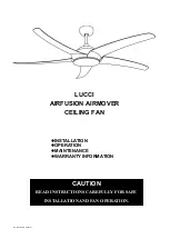
Page 1: ...V1 0 Muti EU WS 10 2018 LUCCI AIRFUSION AIRMOVER CEILING FAN INSTALLATION OPERATION MAINTENANCE WARRANTY INFORMATION CAUTION READ INSTRUCTIONS CAREFULLY FOR SAFE INSTALLATION AND FAN OPERATION...

Page 2: ...s 1 P a g e CONTENTS GB Installation instruction manual 2 D Installationsanleitung 11 F Guide d installation 20 E Manual de instrucciones de instalaci n 29 I Manuale delle istruzioni di installazione...

Page 3: ...ded for use by persons including children with reduced physical sensory or mental capabilities or lack of experience and knowledge unless they have been given supervision or instruction concerning the...

Page 4: ...f electrical appliances are disposed of in landfills or dumps hazardous substances can leak into the ground water and get into the food chain damaging your health and well being 6 The structure to whi...

Page 5: ...are Examine all parts you should have the following 1 Mounting bracket x 1 8 Bottom cover x 1 2 Canopy x 1 9 Blade x 5 3 Down rod with ball joint x 1 10 Wooden screw x 2 4 Coupling cover x 1 11 Extra...

Page 6: ...et to the ceiling joist or structure that is capable of carrying a load of at least 30kg with two long screws provided Ensure at least 30mm of the screw is threaded into the support NOTE The bracket s...

Page 7: ...pin back to the down rod 3 Insert the down rod to the coupling 8 line up the coupling holes with the down rod holes and insert the bolt 10 Then insert the pin 11 to the end of the bolt 4 Finally secu...

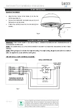
Page 8: ...ocess for the remaining four blades ELECTRICAL WIRING DIAGRAM WARNING FOR YOUR SAFETY ALL ELECTRICAL CONNECTIONS MUST BE UNDERTAKEN BY A LICENSED ELECTRICIAN NOTE AN ADDITIONAL ALL POLE DISCONNECTION...

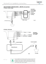
Page 9: ...Airmover Fan Installation Instructions 8 P a g e USE WITH REMOTE WIRING DIAGRAM REMOTE sold separately 1 Remote without plugs 2 Remote with plugs Fig 8 Fig 9...

Page 10: ...power and check the operation of the fan OFF Position Fan off 3rd Position Low fan speed 2nd Position Medium fan speed 1st Position High fan speed Light Control Toggle Switch On off REVERSING SWITCH Y...

Page 11: ...od most noises associated with a new fan disappear during this time The manufacturer s warranty covers actual faults that may develop and NOT minor complaints such as hearing the motor run All electri...

Page 12: ...r Kabelfestinstallation gem den rtlich geltenden Vorschriften f r elektrische Installationen integriert werden 4 Entsorgen Sie elektrische Ger te niemals im regul ren Hausm ll sondern geben Sie das Ge...

Page 13: ...e sollten Folgendes haben 1 Halterung x 1 8 Untere Abdeckung x 1 2 Baldachin x 1 9 Ventilatorfl gel x 5 3 Deckenstange mit Kugelgelenk x 1 10 Holzschrauben x 2 4 Schutzabdeckung des Verbindungsst cks...

Page 14: ...Gewicht von mindestens 30KG tragen kann und verwenden Sie dazu die zwei mitgelieferten Schrauben Stellen Sie sicher dass die Schraubengewinde mindestens 30mm in den Untergrund eingedreht werden HINWEI...

Page 15: ...nge 3 Stecken Sie die Deckenstange durch das Verbindungsst ck 8 Richten Sie die L cher am Verbindungsst ck an den L chern der Deckenstange aus und stecken Sie den Bolzen 10 durch die L cher Stecken Si...

Page 16: ...fl gelschrauben 4 und flachen Unterlegscheiben 2 Wiederholen Sie den Vorgang mit den restlichen vier Ventilatorfl geln ELEKTRISCHES SCHALTDIAGRAMM WARNHINWEIS IM INTERESSE IHRER PERS NLICHEN SICHERHEI...

Page 17: ...irmover Fan Installation Instructions 16 P a g e DER EINSATZ MIT FERNBEDIENUNG SCHALTDIAGRAMM FERNBEDIENUNG ist getrennt erh ltlich 1 Fernbedienung ohne Stecker 2 Fernbedienung mit Stecker Abb 8 Abb 9...

Page 18: ...e die Funktion des Ventilators AUS Stellung Ventilator ist ausgeschaltet 3 Einstellposition niedrige Ventilatorgeschwindigkeit 2 Einstellposition mittlere Ventilatorgeschwindigkeit 1 Einrastposition h...

Page 19: ...gf gige Leistungsschwankungen im Stromnetz sowie den Strom berlagernde Frequenzsignale zur Warmwassersteuerung au erhalb der Sto zeiten k nnen die Ger usche des Ventilatormotors beeinflussen Dies ist...

Page 20: ...ie die separate GARANTIEERKL RUNG KUNDEN IN EUROPA Falls Sie ein Kunde in Europa sind dann treten Sie f r Garantieleistungen bitte mit dem Fachgesch ft in Kontakt wo Sie das Ger t gekauft haben VENTIL...

Page 21: ...nts doivent se faire uniquement sous la supervision d un adulte 2 Les enfants doivent tre surveill s pour qu ils vitent de jouer avec les appareils 3 Il faut incorporer une d connexion tout pole au fi...

Page 22: ...s pi ces il doit y avoir les pi ces suivantes 1 Support de fixation x 1 8 Couvercle inf rieur x 1 2 Cache de fixation x 1 9 Pales x 5 3 Tige avec joint rotule x 1 10 Vis en bois x 2 4 Couvercle de rac...

Page 23: ...urez la bielle de support la solive de plafond ou structure qui sont capable de porter un poids de 30KG avec deux vis longues Assurez qu un moins 30mm de vis a t attach au support NOTE Les vis de supp...

Page 24: ...la cheville sur la tige 3 Ins rez la tige dans le raccord 8 alignez les trous du raccord avec ceux de la tige puis ins rez le boulon 10 Ins rez alors la cheville 11 l extr mit du boulon 4 Enfin fixez...

Page 25: ...orrespondantes 4 et des rondelles plates 2 fournies R p tez l op ration pour les quatre autres pales SCH MA DE C BLAGE LECTRIQUE AVERTISSEMENT POUR VOTRE S CURIT Les branchements lectriques doivent tr...

Page 26: ...n Installation Instructions 25 P a g e UTILISER AVEC LE SCH MA DE C BLAGE DISTANCE DISPOSITIF DE C BLAGE DISTANCE vendu s par ment 1 Dispositif distance sans fiches 2 Dispositif distance avec fiches F...

Page 27: ...on Ventilateur bas r gime 2 me position Ventilateur moyen r gime 1 re position Ventilateur haut r gime Commande de l clairage Interrupteur marche arr t FONCTIONNEMENT INVERS Votre ventilateur peut tre...

Page 28: ...tre des petits bruits occasionnels Les fluctuations de puissance faibles et les signaux de fr quence superpos s dans l lectricit pour les p riodes creuses de ma trise de l eau chaude peuvent provoquer...

Page 29: ...e t l commande Pales de ventilateur 142 cm uniquement 220 240 V CA 85 W N A INFORMATION SUR LA GARANTIE LES CLIENTS D AUSTRALIE NOUVELLE ZEALAND Nous vous prions de r f rer la d claration de garantie...

Page 30: ...con el aparato 3 Debe incorporarse un interruptor con desconexi n de todos los polosal cableado instalado de acuerdo con las normas locales 4 No deseche los aparatos el ctricos en los vertederos muni...

Page 31: ...s las piezas que deber an incluir lo siguiente 1 Soporte mural x 1 8 Cubierta inferior x 1 2 Flor n x 1 9 Aspa x 5 3 Tija con junta esf rica x 1 10 Tornillo de madera x 2 4 Caja del acoplamiento x 1 1...

Page 32: ...tornillos largos suministrados Aseg rese de que al menos 30 mm del tornillo se enrosque en el soporte NOTA Los tornillos del soporte que se proporcionan son para su uso exclusivo con estructuras de ma...

Page 33: ...rsal a la tija 3 Inserte la tija en el acoplamiento 8 alinee los orificios del acoplamiento con los orificios de la tija e inserte el perno 10 A continuaci n inserte el pasador 11 en el extremo del pe...

Page 34: ...efecto 4 y las arandelas planas 2 que se incluyen Siga el mismo procedimiento para las cuatro aspas restantes DIAGRAMA DE CABLEADO EL TRICO ADVERTENCIA PARA SU SEGURIDAD TODAS LAS CONEXIONES EL CTRICA...

Page 35: ...stallation Instructions 34 P a g e USO CON UN DIAGRAMA DE CABLEADO DE UN MANDO A DISTANCIA EL MANDO A DISTANCIA se vende por separado 1 Mando a distancia sin conexiones 2 Mando a distancia con conexio...

Page 36: ...ador apagado Posici n 3 Velocidad del ventilador media baja Posici n 2 Velocidad del ventilador media Posici n 1 Velocidad del ventilador alta Control de iluminaci n Interruptor de cambio conectado de...

Page 37: ...special por la noche puede o r peque os ruidos ocasionales Las ligeras fluctuaciones de corriente y de se ales de frecuencia superpuestas en la electricidad para el control de agua caliente fuera de l...

Page 38: ...er a para control remoto Solo ventilador de aspas de 56 220 240 V CA 85 W N D INFORMACI N SOBRE LA GARANT A CLIENTES DE AUSTRALIA NUEVA ZELANDA Por favor consulte la declaraci n de garant a particular...

Page 39: ...ssere sorvegliati per assicurarsi che non giochino con l apparecchio 3 Un interruttore onnipolare deve essere incorporato nel cablaggio fisso secondo le norme di cablaggio locali 4 Non smaltire appare...

Page 40: ...nti e verificare che corrispondano a quelli elencati di seguito 1 Supporto x 1 8 Coperchio inferiore x 1 2 Calotta x 1 9 Pala x 5 3 Barra inferiore con giunto sferico x 1 10 Vite di legno x 2 4 Coperc...

Page 41: ...o 30 kg con le due viti lunghe fornite Garantire almeno 30 mm della vite filettato nel supporto NOTA le viti della staffa forniti sono per l uso con strutture in legno solo Per strutture diverse da qu...

Page 42: ...e la barra inferiore nel coperchio di accoppiamento 8 allineare i fori del coperchio di accoppiamento con quelli della barra inferiore e inserire il bullone 10 A questo punto inserire lo spillo 11 all...

Page 43: ...viti 4 e due rondelle piatte per le pale 2 in dotazione Seguire la stessa procedura per le altre pale SCHEMA ELETTRICO ATTENZIONE PER LA VOSTRA SICUREZZA TUTTI I COLLEGAMENTI ELETTRICI DEVONO ESSERE E...

Page 44: ...rmover Fan Installation Instructions 43 P a g e USARE CON IL DIAGRAMMA DI CABLAGGIO DEL TELECOMANDO TELECOMANDO venduto separatamente 1 Telecomando senza spinotti 2 Telecomando con spinotti Fig 8 Fig...

Page 45: ...re Posizione SPENTO OFF ventilatore spento 3a Posizione velocit ventilatore medio bassa 2a Posizione velocit ventilatore media 1a Posizione velocit ventilatore alta Controllo luce Premere interruttore...

Page 46: ...mori Leggere fluttuazioni di corrente e segnali di frequenza superimposti nell elettricit per il controllo dell acqua calda fuori picco possono causare un cambiamento nel rumore del motore del ventila...

Page 47: ...a per il telecommando Solo ventilatore 56 pollici 220 240 V CA 85 W N A INFORMAZIONE SULLA GARANZIA CLIENTI IN AUSTRALIA NUOVA ZELANDA Si prega di fare riferimento alla separata DICHIARAZIONE DI GARAN...

Page 48: ...ezicht blijven zodat ze niet met het apparaat kunnen spelen 3 Een tweepolige ontkoppeling moet in de vaste bedrading voorzien worden in navolging van locale elektriciteitsregels 4 Gooi elektrische app...

Page 49: ...er of alle onderdelen aanwezig zijn U moet het volgende hebben 1 Montagebeugel x 1 8 Onderste kap x 1 2 Overkapping x 1 9 Ventilatorblad x 5 3 Neerwaartse stang met kogelgewricht x 1 10 Houten schroef...

Page 50: ...et de twee lange schroeven uit het pakket Zorg ervoor dat tenminste 30 mm van de schroef in het draagvlak geschroefd is OPMERKING De voorziene houderschroeven kunnen alleen in hout gebruikt worden Voo...

Page 51: ...st op de neerwaartse stang 3 Stop de neerwaartse stang in de koppeling 8 breng de gaten op de koppeling op n lijn met de gaten in de neerwaartse stang en breng de bout 10 aan Stop de pen 11 vervolgens...

Page 52: ...behulp van de twee meegeleverde schroeven 4 en platte sluitringen 2 Doe hetzelfde voor de vier andere ventilatorbladen ELEKTRISCHE BEDRADING WAARSCHUWING VOOR UW VEILIGHEID MOETEN ALLE ELEKTRISCHE AAN...

Page 53: ...r Fan Installation Instructions 52 P a g e GEBRUIK MET AFSTANDSBEDIENING SCHAKELSCHEMA AFSTANDSBEDIENING afzonderlijk verkocht 1 Afstandsbediening zonder stekkers 2 Afstandsbediening met stekkers Fig...

Page 54: ...roleer de werking van de ventilator UIT stand ventilator uit 3de Positie laag medium ventilatorsnelheid 2de Positie medium ventilatorsnelheid 1ste positie hoge ventilatorsnelheid Licht Controle Tuimel...

Page 55: ...het stil is vooral s nachts kunt u af en toe kleine geluiden horen Lichte schommelingen in de spanning en frequentiesignalen bovenop de elektriciteit voor warm watercontrole in de daluren kunnen een...

Page 56: ...l vermogen motor Batterij voor afstandsbediening Alleen 56 inch ventilator 220 240 VAC 85W N v t GARANTIE IN AUSTRALIE NIEUW ZEELAND Zie aparte GARANTIEVERKLARING IN EUROPA Als u een Europese klant be...

Page 57: ...Airmover Fan Installation Instructions 56 P a g e Lucci 1 8 2 3 4 5 6 30 7 2 3 2 1 8 2 9...

Page 58: ...Airmover Fan Installation Instructions 57 P a g e 1 x 1 8 x 1 2 x 1 9 x 5 3 x 1 10 x 2 4 x 1 11 x 1 5 x 1 12 x 1 6 x 1 13 x 1 7 x 1 14 x 1 Fig 1...

Page 59: ...Airmover Fan Installation Instructions 58 P a g e 300 mm 30 30 mm 15 Fig 2 3 30...

Page 60: ...Airmover Fan Installation Instructions 59 P a g e 1 6 5 7 2 3 4 2 1 3 8 10 11 4 9 A B C Fig 5 Fig 4...

Page 61: ...Airmover Fan Installation Instructions 60 P a g e 3 1 4 2 FAN Brown Orange 7 Fig 6...

Page 62: ...n and Light Neutral Earth TERMINAL BLOCK IN MOUTING BRACKET WALL CONTROLLER SUPPLY INPUT 220 240VAC 220 240VAC ROTARY SWITCH Speed 1 1 Speed 2 2 Speed 3 3 LIGHT SWITCH 1 220 240Vac Power supply from c...

Page 63: ...2 P a g e To motor L L For light TO motor N N Connection plug 2 220 240Vac Power supply from ceiling 220 240Vac L live L N Neutral N Earthing Brown Blue Green Yellow Connect together Input Remote rece...

Page 64: ...Airmover Fan Installation Instructions 63 P a g e OFF 3 2 1 10 11...

Page 65: ...Airmover Fan Installation Instructions 64 P a g e REVERSING SWITCH 24 12...

Page 66: ...Airmover Fan Installation Instructions 65 P a g e Aria 56 220 240 VAC 85W...

Reviews: