background image

Airfusion HAVANA Installation Instructions 


10 | 

P a g e  


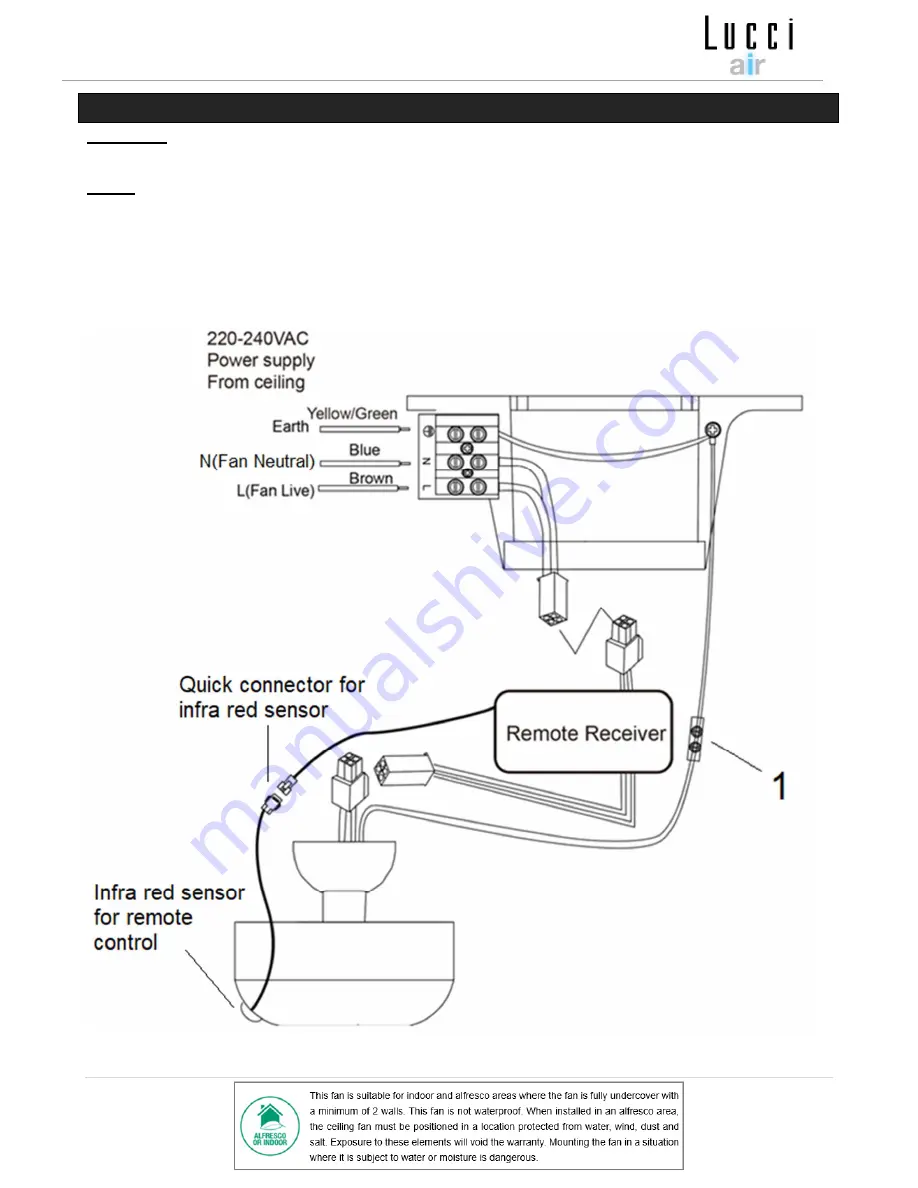
ELECTRICAL WIRING DIAGRAM 

WARNING:

FOR  YOUR  SAFETY  ALL  ELECTRICAL  CONNECTIONS  MUST  BE  UNDERTAKEN  BY  A 

LICENSED ELECTRICIAN.


NOTE:

AN  ADDITIONAL  ALL  POLE  DISCONNECTION  SWITCH  MUST  BE  INCLUDED  IN  THE  FIXED 

WIRING. 


Ensure the motor earth wire is connected to the single earthing terminal block “1” in the diagram 

below. (Fig. 11) 


Fig. 11 

Summary of Contents for AIRFUSION HAVANA

Page 1: ...V1 0AU 2019 12 LUCCI AIRFUSION HAVANA CEILING MOUNTED OSCILLATING FAN INSTALLATION OPERATION MAINTENANCE WARRANTY INFORMATION CAUTION READ INSTRUCTIONS CAREFULLY FOR SAFE INSTALLATION AND FAN OPERATION ...

Page 2: ...vision 2 In Australia The appliance is not intended for use by persons including children with reduced physical sensory or mental capabilities or lack of experience and knowledge unless they have been given supervision or instruction concerning the use of the appliance by a person responsible for their safety 3 Children should be supervised to ensure that they do not play with the appliance 4 An a...

Page 3: ...n Australia Refer to the Clearance requirement section for more information 9 This fan is suitable for indoor and alfresco areas where the fan is fully undercover with a minimum of 2 walls This fan is not waterproof When installed in an alfresco area the ceiling fan must be positioned in a location protected from water wind dust and salt Exposure to these elements will void the warranty Mounting t...

Page 4: ...or replacement Check whether the ceiling fan has been damaged during transport Do not operate install any product which appears damaged in any way Return the complete product to the place of purchase for inspection repair or replacement Examine all parts you should have the following 1 Mounting bracket x 1 2 Fan motor assembly x 1 3 Fan blade bracket x 1 4 Fan bladesx 3 5 Fan blades fixing cap x 3...

Page 5: ... the floor In Europe NOTE The lowest point of the fan blade is when the fan head is adjusted to 45 The ceiling fan must be installed in a location so that the blades are a minimum1M spacing from the tip of the blade to the nearest objects or walls NOTE Please be aware of that the fan head can be oscillating 60 Please take this into consideration when selecting the installation location Fig 2 ...

Page 6: ... Ensure at least 30mm of the screw is threaded into the support Fig 3 NOTE The bracket screws provided are for use with wooden structures only For structures other than wood the appropriate screw type MUST be used Ensure the screws used are suitable for the mounting surface and the surrounding environment ANGLED CEILING INSTALLATION This fan hanging system supportsa maximum 13 degree angled ceilin...

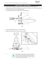
Page 7: ... blade bracket 2 Insert the fixing cap 4 into the mouting holes from the bottom of the blade 3 and secure by tightening the 3 screws 1 from the top of the blade bracket 2 Once completed repeat the same process on the remaining blades Install the assembled fan blades 7 to the motor part 5 Tighten the 2 set screws 6 on the side of the motor shaft Fig 5 Fig 6 ...

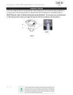
Page 8: ...he hanger ball is positioned on the key pin B of the mounting bracket C to prevent the fan from rotating when in operation Fig 7A NOTE Please be aware of that the fan head can be oscillating 60 There are key slots Fig 7B provided on the hanger ball which allow you to adjust the direction of the fan according to your requirement Fig 7A Fig 7B ...

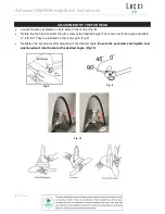
Page 9: ... Fig 8 Rotate the fan head and aim the arm screw at the desired angle There are only three angles available 0 45 90 They are labelled on the motor part Fig 9 Retighten the set screws after adjusting to the desired angle Ensure the set screws are tighten and postioned well into the slot of the desired angle Fig 10 Fig 8 Fig 9 Fig 10 ...

Page 10: ...FOR YOUR SAFETY ALL ELECTRICAL CONNECTIONS MUST BE UNDERTAKEN BY A LICENSED ELECTRICIAN NOTE AN ADDITIONAL ALL POLE DISCONNECTION SWITCH MUST BE INCLUDED IN THE FIXED WIRING Ensure the motor earth wire is connected to the single earthing terminal block 1 in the diagram below Fig 11 Fig 11 ...

Page 11: ...t using the screws provided Fig 11 Switch ON mains power supply to the fan Test the fan operations or enjoy using the fan following instructions the under USING YOUR CEILING FAN section of this instruction manual USING YOUR CEILING FAN BATTERY INSTALLATION IN THE REMOTE CONTROL Fig 13 Your ceiling fan is controlled by the remote control The following must be considered before operating the remote ...

Page 12: ...d automaticly after the time you selected 4 60 Oscillation On Off The transmitter and receiver are communicated by infra red signal The remote controller must be operated within the following distances Approximately 45 from the infra red sensor to the left right Distance from transmitter to the infra red sensor Max 3 meters NOTE The remote has memory function if the mains power is turned off It wi...

Page 13: ...bracket and down rod are secure NOISE When it is quiet especially at night you may hear occasional small noises Slight power fluctuations and frequencysignals superimposed in the electricity for off peak hot water control may cause a change in fan motor noise This isnormal Please allow a 24 hour settling in period most noises associated with a new fan disappear during this time The manufacturer s ...

Page 14: ...teries must be removed from the remote transmitter before it is discarded Always use Lithium CR2032 battery type with this ceiling fan remote controller Dispose of exhausted batteries immediately and safely so they cannot be retrieved by children Flat batteries can still be dangerous Contact your local council to safely dispose of the battery Ensure the batteries are inserted with the correct pola...

Page 15: ...llating fan Model No SKU LD 15 HAVA ORB SKU 213160 LD 15 HAVA BLK SKU 213161 LD 15 HAVA CHW SKU 213162 Colour Orb Black White Rated Voltage 220 240V 50Hz Rated Wattage 55W 51W fan motor 4W oscillation motor Battery for remote CR2032 3V Weight 3 8kg Size Dia 380mm H 550mm Max Canopy Dimensions H 60mm Dia 130mm ...

Page 16: ... as a result of normal wear and tear 3 The product was installed by a licensed electrical contractor 4 A copy of the original receipt of purchase is presented 5 12 month warranty applies when used in any non domestic applications 6 This warranty does not cover stains scratch and scuff marks or dents if the product is purchased through a factory outlet or to refurbished items Our goods come with gu...

Page 17: ...for your personal records and warranty purposes NAME ADDRESS POSTCODE MODEL NUMBER PO DATECODE Sticker here PO NUMBER or DATECODE DATE OF PURCHASE INSTALLING LICENSED ELECTRICIAN LICENCE No ATTACH PROOF OF PURCHASE HERE THIS COMPLETED DETAIL PAGE SHOULD BE PRODUCED AND FAXED TO THE WHOLESALER OR THEIR AUTHORISED AGENTS BEFORE OBTAINING WARRANTY SERVICE ...

Reviews: