background image

ISDN DEFINITY

 Extender 2300EU/2100EU

22

Configuring Using a Terminal
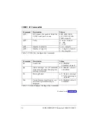
Saving ISDN
Changes

If you modified any ISDN parameters, the terminal will
prompt you with the option to Save ISDN Changes?:

1)


Type to save the changes.

OR

1a)


Type N to discard the changes.
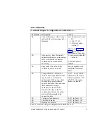
System Menu

The System Menu provides you with access to configure:


Passwords


COM port settings


Set ISDN Connect Rate


Show Settings


Software Upgrade

Passwords

The System Administrator is the person responsible for
configuring Passwords.  Selecting this menu item from
the main menu will prompt the user for the System
Administrator’s password.

Summary of Contents for 2100EU

Page 1: ...ISDN DEFINITY Extender Models 2300EU and 2100EU System Administrator s Guide Document 555 025 118 Comcode 108478421 Issue 1 February 1999 ...

Page 2: ...authorized use of common carrier telecommunication services or facilities accessed through or connected to it Lucent Technologies will not be responsible for any charges that result from such unauthorized use Lucent Technologies Fraud Intervention If you suspect that you are being victimized by toll fraud and you need technical support or assis tance call your local Lucent representative Federal C...

Page 3: ...n 2 Product Family 3 How the Connection Works 4 Checklist 5 Introduction 6 Switch Module Checklist 7 ISDN Line Checklist 8 PC or Network Connection 5 Environment Checklist 9 Electrical Checklist 9 Quick Configuration Guide 10 Introduction 10 Configuring and Installing the Switch Module 10 Verifying Configuration 13 Powering Up Down 13 ...

Page 4: ...ng ETI TTI Menu 15 Terminal Edit Line 16 Configuring The Switch Module 17 Setting ISDN Parameters 18 Setting DN1 16 Setting DN2 17 Setting the TEI Type 18 Saving ISDN Changes 22 System Menu 22 Passwords 22 Configuring the COM Port 23 Setting Data Rate 21 Setting Parity 21 Setting Data Bits 21 Setting Stop Bits 22 Show Settings 25 Software Upgrades 25 ...

Page 5: ...C Connector 28 Hardware Flow Control 28 2100EU Terminal Information 29 Introduction 29 Description 29 Typical Connections 29 Typical Operation 30 Setting the PC Modem 31 2100EU TA Configuration 32 Introduction 32 Changing Terminal Adapter Settings 32 Setting the Data Rate 32 Setting Parity 33 Setting Data Bits 33 Setting Stop Bits 33 ...

Page 6: ...ction 34 Terminal Adapter Configuration Commands 36 Terminal Adapter Action Commands 39 AT Result Codes 39 Software Upgrading 41 Introduction 41 Obtaining the Upgrade File 41 Upgrading the Serial Port 40 Verify Upgrade 44 Upgrading from the Remote Module 45 Verifying the Switch Upgrade 47 ...

Page 7: ... 50 LED Error Indicator Sequences 51 Serial S Record Upgrade Errors 53 Cannot Upgrade Software 53 Upgrade Failed 53 ISDN Upgrade Errors 53 PBX Flash Too Small 53 REM Flash Too Small 53 Upgrade Start Failure 54 Flash Erase Failure 54 Flash V Erase Failure 54 UG Data Timeout Failure 54 Data End Timeout Failure 54 UG CRC Timeout Failure 54 Diagnostic Statistics 55 Error Codes 52 Exclusive Error Codes...

Page 8: ...Table Of Contents ISDN DEFINITY Extender 2300EU 2100EU Equipment Attatchment Limitations 67 Glossary 69 ...

Page 9: ...te Troubleshoot Prerequisite This manual was written with the assumption that you possess a working knowledge of Lucent digital phones and the DEFINITY Enterprise Communications System ECS Should you require further information on how the phone or ECS works we suggest you either consult your Lucent Technologies system administrator or read the user documentation provided with your phone system ...

Page 10: ...ansfer calls set up conference calls have a corporate based receptionist screen calls access the voice mail auto attendant or any other software residing on the ECS Extenders work with existing corporate digital telephone sets but there are restrictions to telephone use at residential locations Transmission is over the public telephone network using ISDN or BRI lines A Switch Module and a Remote M...

Page 11: ...e via the built in S T interface The Switch Module connects to a digital port on the ECS located at the corporate office and the Remote Module connects to a Lucent digital phone set at a remote location The ISDN DEFINITY Extender Models 2300EU and 2100EU includes MCK s Interactive Voice ProtocolTM software The software packetizes compresses and encrypts voice and ECS signals to condition them for ...

Page 12: ...annel establishes a 64 Kbps digital link The second B channel will have one of the following capabilities depending on the model you have 2300EU Analog Port 2100EU Analog Port RS232 Terminal Adapter Note The Analog Port is only available on the Remote Module Speech is compressed to 32 Kbits ADPCM format and is combined with the telephone signaling data and COM port data for 2300EU Once the install...

Page 13: ...DR This display telephone is certified for residential use 8434D Requires a separate power supply NOTE The power supply that comes with the ISDN Remote Module cannot produce the power required by the 8434D telephone An MSP 1 WP924644 power supply must be used Check with your Lucent Technologies representative for ordering information 603 E Callmaster III 603F1 Callmaster IV Callmaster VI This PC b...

Page 14: ...ISDN DEFINITY Extender 2300EU 2100EU 6 Checklists Introduction Before continuing with the installation and configuring of your Switch Module please go through the following checklists ...

Page 15: ...r 240 volt AC adapter One RJ45 line cord The following services should be installed and tested before proceeding DEFINITY ECS digital port DEFINITY ECS BRI port or ISDN line as described in the ISDN line checklist Parts required to configure the Switch Module but NOT included with the system PC or terminal with a terminal emulation package must be VT100 compatible RS232 serial cable Male DB9 conne...

Page 16: ... technological or manufacturing changes warrant Ensure you have the proper ISDN line installed at the switch site Ensure you know the DN numbers and TEI type You obtain this information from your local ISDN service provider when the ISDN lines are installed Ensure that you have registered the ISDN lines with your long distance carrier for ISDN DATA Service if required PC or Network Connection If y...

Page 17: ...with a relative humidity below 95 Free of any large electrical equipment such as copiers or motors that generate electromagnetic radio frequency and electrostatic interference Within 150 meters 500 feet of the DEFINITY ECS Electrical Checklist The AC electrical requirement for the ISDN DEFINITY Extender Models 2300EU and 2100EU is 12 volt DC unregulated supplied by 220 or 240 Volt adapters ...

Page 18: ...nd 2100EU see Figure 1 Figure 1 Switch Module Back Panel 1 Plug the Switch Module port labeled PHONE SWITCH on the Module back plane into the DEFINITY ECS using the RJ45 cable 2 Plug the Switch Module ISDN interface labeled ISDN into the ISDN line provided by the DEFINITY ECS or your service provider using the RJ45 cable 3 Plug the male DB9 end of the RS232 cable into the Switch Module connector l...

Page 19: ...d red blinks After 10 seconds of very fast red blinking the LED will blink green three times and red once The LED will then blink 3 sets of 8 yellow flashes NOTE You can only access the menu on power up 5 During this yellow flash sequence type the word MENU After you have entered the command the Switch Configuration menu will appear on the terminal program 6 Select Configure ISDN to configure the ...

Page 20: ... are using the Switch Module for your data connection write down the DN2 number You will need it to program your remote data equipment 8 After the ISDN parameters are entered exit the Configure ISDN menu You will be prompted to save the new ISDN parameters 9 Select Yes The Switch Module will initialize to the ISDN network at this time Access the Configure System menu from the Main menu 10 Set Pass...

Page 21: ...ring Up Down NOTE Before powering down the Switch Module ensure that you are offline 1 Unplug the AC adapter from the back of the Switch Module 2 Disconnect the ISDN line and ECS digital port 3 Reconnect the ISDN line and ECS digital port 4 Plug the AC adapter to the back of the Switch Module After the powering up your Switch Module LED should blink a three green flash sequence indicating it is no...

Page 22: ...its Stop Bits Optional For the 2300EU the COM Port settings are for the serial data connection that shares the first B channel For the 2100EU the COM Port settings are for the RS232 data port that uses the second B channel Requirements When configuring the Switch Module ensure the PC or terminal has its communications parameters set to 9600 BPS No parity 8 bits 1 stop bit The Switch Module must be...

Page 23: ...C doesn t have VT100 terminal emulation you need to use the TTI menu which is accessed after the ETI menu displays The ETI menu will be unrecognizable but you still access the TTI menu from this point Accessing the ETI TTI Menu To access either configuration menu 1 Plug in the Switch Module s RS232 serial port to a PC with a terminal application When the Switch Module is powered up the module will...

Page 24: ...inal Edit Line The Terminal Edit Line is where features can be entered or modified When editing parameters on the terminal edit line current parameters will be highlighted if previously entered For both the ETI menu and the TTI menu the following edit line key strokes can be used to modify parameters You can select a menu item by pressing A hot key the number of the menu item The arrow up and arro...

Page 25: ...d parameter or the Backspace key to erase the character to the left of the cursor Left Arrow and Right Arrow keys to move through the parameter being edited The Enter key to accept the changes Configuring the Switch Module Once the main menu is displayed using either method the following configuration selections can be accessed Configure ISDN allows you to configure the ISDN parameters Configure S...

Page 26: ...ameters To connect the Switch Module to the ISDN Network the following ISDN Parameters may require configuring The ISDN Network Switch Type The two Directory Numbers DN numbers The TEI type From the Main Menu press 1 For the Configure ISDN menu to access the ISDN Parameter sub menus ...

Page 27: ... for Set DN1 from the Configure ISDN menu If a previous DS1 number was stored the display shows that number If no DN number was stored the display is blank 3 Enter the first DN for the Switch Module up to 15 digits in length 4 Press Enter to accept the change You automatically return to the Configure ISDN Menu To save your changes if you are finished programming Exit from the Configure ISDN Menu T...

Page 28: ... for Set DN2 from the Configure ISDN menu If a previous DN2 number was stored the display shows that number If no DN2 number was stored the display is blank 3 Enter the second DN for the Switch Module up to 15 digits in length 4 Press Enter to accept the change You automatically return to the Configure ISDN Menu To save your changes if you are finished programming Exit from the Configure ISDN Menu...

Page 29: ...s not provided you with a fixed TEI value If a fixed TEI is provided select Fixed TEI type From the ISDN Configuration menu 1 Press 6 to set TEI Type 2 Toggle between FIXED and AUTO 3 Press Exit to save the selection If you select FIXED TEI press SET TEI1 If you selected FIXED TEI type 1 Press 7 to Set TEI1 2 Enter the TEI number of the switch site 0 63 3 Press Return to save the number If you cha...

Page 30: ...Y to save the changes OR 1a Type N to discard the changes System Menu The System Menu provides you with access to configure Passwords COM port settings Set ISDN Connect Rate Show Settings Software Upgrade Passwords The System Administrator is the person responsible for configuring Passwords Selecting this menu item from the main menu will prompt the user for the System Administrator s password ...

Page 31: ... communications The 2300EU multiplexes voice and data across the first B channel On the 2100EU the COM port uses the second B channel This section describes the steps involved to program the RS232 port 1 From the System Menu select COM to access the following sub menus Data Rate Parity Data Bits Stop Bits NOTE All COM port settings should be configured at one time ...

Page 32: ...tion the Parity menu will appear Setting Parity To change Parity 1 Highlight the Parity you want and press Enter Your choices are None Even or Odd OR 1a Press the hot key of the Parity you want When you make your selection the Data Bits menu will appear Setting Data Bits To change the Data Bit setting 1 Highlight the desired Data Bit and press Enter Your two options are 8 or 7 data bits OR 1a Pres...

Page 33: ...ay the current module Settings 1 Highlight Show Settings 2 Press Enter All system settings will be displayed Software Upgrades All ISDN DEFINITY Extender Models 2300EU and 2100EU units can be software upgraded Selecting this menu item prepares the module for a Serial port Software Upgrade For details see the Software Upgrading section later in this manual This menu option is not required for initi...

Page 34: ... shared first B channel An RS232 serial port on the second B channel The RS232 COM port that shares the first B channel is available on the 2300EU The RS232 port on the second B channel is available on the 2100EU The 2100EU is capable of asynchronous to synchronous PPP over the RS232 port This can be used to establish a data connection using Windows Dial up Networking The 2100EU will be discussed ...

Page 35: ...the RS232 communication link refer to the user documentation included with your data system for the required cable types and pinouts The Switch and Remote Module will require a male DB9 cable end to connect to the RS232 port standard RS232 as described on the next page Connecting the other cable end to your LAN will depend on the physical type and format the LAN uses Talk to your Information Servi...

Page 36: ...Send PIN 8 CTS Clear To Send Table 1 RS232 COM Port Pin Out Hardware Flow Control The COM Port uses hardware flow control to manage the data throughput Ensure that the cables and network hardware you use have the proper hardware flow control connections to prevent lost data Note To use the 2300EU for simultaneous data access you must make sure that the COM port settings for your Remote Module remo...

Page 37: ...an RS232 serial cable to the DB9 female connector on the Remote Module labeled RS232 and connect the other end to the Remote PC If you are going to connect the Switch Module to a Windows NT Remote Access Server an RS232 cable should be connected from the connector labeled RS232 on the Switch Module to a COM port also could be on a COM port off a Digi port on the Remote Access Server If you are goi...

Page 38: ...Table 2 RS232 COM Port Pin Out Typical Operation When a Dial up Networking connection is initiated the remote PC establishes a connection to a Remote Access Server Essentially your remote PC will be connected to your office network with its full capabilities as if you were in the office A Dial up Networking connection on the PC may also be configured to make a connection to an Internet Service Pro...

Page 39: ...NEXT 5 Check the box for Don t detect my modem I will select it from a list Press NEXT 6 Select Motorola for manufacturer 7 Select BitSURFR as the model Press NEXT 8 Select the COM Port on the PC that will be used Press NEXT 9 Select FINISH Return to the Modems folder General window 10 Select the modem you created 11 Select Properties 12 Select 57600 as the maximum speed Have your Information Serv...

Page 40: ... involved to program the terminal adapter configuration NOTE You must be in the Menu on the Switch Module to configure the terminal adapter settings 1 From the Configure System menu select COM All COM port settings are configured at one time 2 Press Enter Setting The Data Rate To set the Data Rate 1 Highlight the data rate you require Data rate options are 2400 4800 9600 115 2 19200 38400 57600 an...

Page 41: ...its menu will appear Setting Data Bits To change the Data Bit setting 1 Highlight the desired Data Bit Your two options are 8 recommended or 7 data bits 2 Press Enter When you make your selection the Stop Bits menu will appear Setting Stop Bits To change Stop Bits 1 Highlight the Stop Bit format you want Your options are 1 recommended or 2 stop bits 2 Press Enter You will now automatically return ...

Page 42: ...ands to the left of it will have been executed If the command consists solely of a letter followed by a number e g Qn omitting the number in place of the n is the same as specifying 0 For example ATQ is the same as ATQ0 Also following the letter with a question mark will display the current value for the configuration parameter For example ATE will display the current value for the local echo conf...

Page 43: ... both B channels 1 N1 DN 1 The directory number for the first B channel 1 15 digits 2 N1 DN 2 The directory number for the second B channel 1 15 digits V View the ISDN parameters G View ISDN switch type C View DNs and TEIs W Save active ISDN configuration Z Replace active ISDN configuration with the saved settings Table 1 ISDN Configuration Commands ...

Page 44: ...it default 2 two stop bits Table 2 COM1 Port Configuration Commands Command Description Values En Local echo n 0 Disabled 1 Enabled default Qn Status messages are AT command responses and connection progress messages displayed n 0 Enabled default 1 Disabled Vn Message format n 0 Numeric messages 1 Verbose messages default Wn Carrier Protocol result codes are carrier and protocol messages displayed...

Page 45: ... S1 Ring count The value of this command never increments 000 Compatible with BitSURFR command lines S2 Escape character defines the value of the escape character that may be used to exit from the online mode If there is no data for an interval greater than or equal to the Guard Time and then three consecutive escape characters are received the module will return to the AT command mode from the on...

Page 46: ...connection n 0 always on 1 tracks connection default Dn Data Terminal Ready Sets how the module handles the DTR signal from the PC n 0 ignore DTR 1 Return to AT command mode from online mode connection remains active 2 Disconnect the call and return to AT command mode default A2 Select the protocol used on the ISDN connection 95 PPP default A95 Accept incoming data calls D do not answer E answer d...

Page 47: ...ands Command Description Values A Answer an incoming call D Initiate an ISDN call 0 9 For backwards compatibility the D may be followed by P T or W H Hang up a call O Return back to online mode from AT command mode Table 4 Terminal Adapter Action Commands AT Result Codes The following codes may be returned after an AT command is executed Depending upon the value of the message format configuration...

Page 48: ... encountered in the AT command line Commands to the left of the erroneous command were executed 6 NO DIALTONE No dial tone was detected when trying to place a call 7 BUSY The called number was busy or the second EXT 3000t B channel was already in use for a POTS call 17 CONNECT 56000 A connection was established at 56 Kbps 19 CONNECT 64000 A connection was established at 64 Kbps 79 PROTOCOL PPPC Th...

Page 49: ...y of the new release The ISDN Upgrade which requires a Remote Module with the latest software connecting with a Switch Module The latest software upgrade is stored internally in non volatile FLASH memory Obtaining the Upgrade File To download new software in the serial mode you need a soft file that contains the latest software release This file is in a special format called S Record and is availa...

Page 50: ...e to allow access to the extender s configuration menu using the terminal Please refer to the section Configuring Using A Terminal if you require further information Using the terminal emulation package configured for VT100 ensure the data rate is set to 9600 bps 1 stop bit no parity 1 Power up the extender The module s LED will perform a series of yellow green and red blinks After 10 seconds of r...

Page 51: ...ill display the following messages Last chance to stop The Flash memory will be erased Do you want to continue Enter Y to continue any other key to abort 5 Enter Y to continue The following message will be displayed Please wait while flash memory is being erased The erase process takes about 15 seconds The message Erasing Flash Memory is displayed as Flash ROM is being prepared to receive the new ...

Page 52: ... lines The process can take 10 or more minutes depending on the size of the file When completed the display will show the following message The file was captured and stored to flash with no errors Verifing Upgrade Once downloaded the new code release is verified by checking the new code s CRC Cyclical Redundancy Check The module then displays Verifying new code If the test passed the terminal will...

Page 53: ...n to the Go Online menu 2 Record your PBX Dial Number by entering the PBX dial number you normally use to go online with your Switch Module 3 Change the PBX Dial Number to dial the Switch Module that you need to upgrade 4 Go online with the Switch Module to be upgraded 5 Enter Administrator s password 6 While online press the HOLD key four times to enter the online menu If the code version you are...

Page 54: ...No or 3 to abort The LCD will display Starting PBX Upgrade followed by Erasing Flash at PBX and finally the upgrade status 0 Completed The percentage value will increase as the upgrade proceeds and depending on the size of code release will take a couple of minutes The new software is being stored to the FLASH memory on your Switch Module When the upgrade is 100 completed the new code is downloade...

Page 55: ... the code size Your remote phone will display Upgrade Successful The remote phone will prompt you with the question Restart Units Even though the new code has been loaded into your Switch Module s FLASH memory your Switch Module is still running your old code Press Ok or 2 to invoke a disconnection from the Switch Module and restart your Switch Module with the newly downloaded code If you encounte...

Page 56: ...operly seated Ensure you are using the Remote Module at the remote site and the Switch Module at the switch site Verify the ISDN DEFINITY Extender Models 2300EU and 2100EU LEDs are flashing Eliminate potential causes of interference Check the error message on the telephone Verify the ISDN parameters and Dial Numbers No Remote Site Phone Display Ensure you have a Remote Module and not a Switch Modu...

Page 57: ...N parameters No Indicator Lights At Power Up Ensure the AC power adapter is connected to the ISDN DEFINITY Extender Models 2300EU and 2100EU module Ensure the AC power outlet is working Check it with some other electrical device The module may not be operational see LED sequences on next page Switch Module Will Not Answer Someone in the office could be using the port and is unaware you are trying ...

Page 58: ... DRAM Data test failed Yellow 2 Red DRAM Address test failed Yellow 3 Red DUART test failed Yellow 7 Reds 1 Green Passed all hardware tests Table 6 LED Power Up Sequences LED Power Up Verification Sequences LED Sequence Description Rapidly blinking Red during process and then 1 Green to indicate process is complete 10 15 seconds FLASH code is being verified and if valid will be executed 25 30 seco...

Page 59: ...mote Module is not operational 3 Red or 4 Red If you have not tried to place or receive a call then the Extender is functioning normally If you have tried to place or receive a call there is a network error 1 Green 0 Red or 1 Red or 2 Red Unit is online with the Switch Module B1 Data connection is not established 2100EU Data connection is established 2100EU Data B2 dialing for connection 2100EU Ta...

Page 60: ...00EU Data connection is established 2100EU Data B2 dialing for connection 2100EU 3 Green 0 Red or 1 Red or 2 Red Phone display is Go Online B1 Data connection is not established 2100EU Data connection is established 2100EU Data B2 dialing for connection 2100EU 1 Red 1 Yellow 1 Green Fatal Error Contact Customer Support Table 8 LED Indicator Sequences cont d For Remote Module only ...

Page 61: ...ctly and you will have to contact Customer Support Verify failure with Power up LED Sequences three red LED flash failure Upgrade Failed If the upgrade failed attempt the download procedure again If you encounter consistent failures consider using the ISDN Upgrade procedure or contacting Customer Support Refer to Cannot Upgrade Software section ISDN Upgrade Errors The following upgrade errors may ...

Page 62: ... hardware problem Power down upgrade unit and retry Flash V Erase Failure The Flash memory did not successfully erase test Retry upgrade If it continues to fail the destination module has a Flash memory hardware problem UG Data Timeout Failure The Remote Module was expecting a response but did not receive it within the required time The upgrade failed Data End Timeout Failure The upgrade failed UG...

Page 63: ...ing an ISDN error event occurred Errors are displayed as a code number and letter The letter represent the severity of the error increasing in severity from A to C as follows A Could occur regularly A common error that should not directly impair Extender operation For example out of sequence ISDN packets B Should not occur often Something has been unplugged or if it goes online without the PBX con...

Page 64: ...synchronized 108B Number of times Signaling channel had no data for 16 consecutive seconds 109A Number of times Signaling channel timed out waiting for packet acknowledgment 110C Number of times Signaling channel transmit locked up transmit buffers full when no data to send 111A Number of Rejected Received ISDN User Data packets because they were out of sequence 112B Number of times Maximum number...

Page 65: ...cked up 125B Number of fatal errors that caused unit to restart caused by errors 124C 118C and 120B Error codes 101 to 125 are directly compatible with 2000 error codes Exclusive Error Codes Error code Description 126C Invalid Length of SCC Tx packet 127B SCC Transmit Busy 128A SCC Rx Status Error 129A SCC Tx Status Error 130A Invalid Voice Packet ID detected 131A Number of Times all user data Buf...

Page 66: ...ng The Statistics After viewing Diagnostics Statistics to determine a problem with your system and you no longer require the messages displayed the statistics need to be reset 1 Press 3 until the display shows Reset Stats OR 1a Press 2 The statistics are now reset ...

Page 67: ...isplay a Connection Error This error may indicate a line condition problem or a configuration problem that is causing the Remote and Switch Modules to not complete a successful connection or break the existing connection Table 10 lists all possible Connection Errors that could be displayed likely causes of the error condition and suggestions actions to correct the error ...

Page 68: ...emote Module connects to the line Channel in Use At times when the Extender places a call if the previous call failed to connect the network requires a delay between the next call attempt If you do not wait long enough this message is displayed If connection fails re attempt to Go Online No Free L4 Buff If this error is displayed please contact Customer Support No Dial Tone Invalid number entered ...

Page 69: ...t Call progress time out The module was waiting for a message from the network that did not receive Possible ISDN network problem User Abort Displayed when the user hits the Drop Redial key three times to abort the connection process V42 Connect Fail The Remote and Switch Modules connect but the IVP does not synchronize Possible ISDN Connect rate problem Your Switch Module ECS digital port may be ...

Page 70: ...dule was disconnected from the Switch Module No SCC Transmit If continues to be displayed then possible hardware problem Contact Customer Support Problem Continue If you are still experiencing difficulties the suitability of the phone lines is in question Check with your phone company to ensure the line requirements have been met ...

Page 71: ...ut The unit is in Dialback mode and the Remote came out of COD but never received a Dialback call from the Switch module Switch unit could not place an ISDN call to the Remote ISDN Conn Lost The unit comes out of COD mode and successfully connects but the connection is lost Note If placing an outgoing call the unit tries to reconnect Connectivity problems with the ISDN network V 42 Failed The unit...

Page 72: ...led The units wake out of COD and successfully establish a connection but the Remote was unable to establish a V 42 connection to the Switch module Data problems on the ISDN network ISDN Conn Failed The units attempt to wake out of COD mode but are unable to establish an ISDN connection Connectivity problems with the ISDN network ...

Page 73: ...nown Error Unknown fatal error occurred on previous power up Fatal Error Messages Message Description No DSP Response If the DSP is not operating correctly contact Customer Support Port Disconnected The Digital port at the Remote Module was disconnected during normal operation No SCC Transmit If it continues to be displayed then possible hardware problem Contact Customer Support Table 11 The fatal...

Page 74: ...SDN DEFINITY Extender 2300EU 2100EU 66 Troubleshooting Customer Support Information If you need assistance when installing programming or using your system contact your Lucent Technologies representative ...

Page 75: ... method of connection In some cases the company s inside wiring associated with a single line individual service might be extended by means of a certified connector assembly telephone extension cord The customer should be aware that compliance with the above conditions might not prevent degradation of service in some situations Any repairs or alterations made by the user to this equipment or equip...

Page 76: ...ld not attempt to make such connections themselves but should contact the appropriate electric inspection authority or electrician There are no user serviceable parts inside this equipment Mention of third party products are for informational purposes only and constitutes neither endorsement or recommendation of product ...

Page 77: ...s no activity and reconnects the modules when activity occurs Central Site Lines Communication lines usually twisted pair that are used to connect the DEFINITY ECS to the DEFINITY telephone D DCD Data Carrier Detect A signal from the DCE modem or printer to the DTE typically your PC indicating the modem is receiving a carrier signal from the DCE at the other end of the telephone cicuit Dedicated S...

Page 78: ...ry Numbers for each module one to dial the module and one to dial the PC server or fax machine analog modem or analog telephone connected to the module DTE speed The speed at which the COM1 serial port runs DTR Data Terminal Ready A control signal sent from the DTE to the DCE that indicates that the DTE is powered on and ready to communicate DTR can also be used for hardware flow control E EU Euro...

Page 79: ...DEFINITY Extender module that connects to the remote DEFINITY telephone S Service Profile Identifier A Service Profile Identifier SPID is a number that identifies to the ISDN network the type of service to be provided Each SPID is attached to a Directory Number Each module must be programmed with two SPIDs one for each Directory Number See Directory Number Switch Module The DEFINITY Extender modul...

Page 80: ...y T TEI Terminal Endpoint Identifier Up to eight devices can be connected to one ISDN BRI line The TEI defines which device is communicating with the Central Office Switch TTI Text Terminal Interface The fax machine s telephone number and user name ...

Reviews: