7.
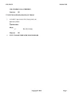
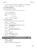
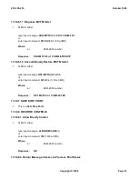
At the MCTSI cabinet, side 0 PCD pack, depress the
ON
button.
Response:
REPT PWR ON MCTSI=
a
-0
Where:
a =
EXM-2000 number
8.
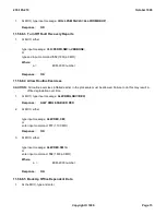
At MCC page 1190 diagnose MCTSI-0, enter input command
500
9.
Did MCTSI-0 pass all diagnostics?
If,
YES
, continue with next Step.
If,
NO
, resolve problem, contact next level of technical support as required. Do not continue until problem is
resolved.
10.
At MCC page 1190, are MCTSI-0 external clock references 0 and 1 in
STBY
state?
If,
YES
, continue with next Step.
If,
NO
, resolve problem, contact next level of technical support as required. Do not continue until problem is
resolved.
11.
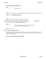
Observe a 15 minute soak period.
NOTE:
Should problems occur, contact the next level of technical support and resolve problem. Do not
continue until problem is resolved.
11.56.5.3 Install MMSU Scan Points
1.
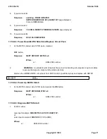
Select customer-supplied RCV 8.11 forms identifying BITS BOX scan points.
2.
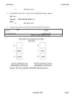
From the DCD-523, cross connect terminals (two audible
minor
alarms), connect to an available pair of scan
leads from the MMSU. Record scan point used for the minor alarm connection.
3.
From the DCD-523, cross connect terminals (two audible
major
alarms), connect to an available pair of scan
leads from the MMSU. Record scan point used for the major alarm connection.
4.
Select and prepare terminal for recent change and verify (RCV) activities.
Reference:
Procedure 11.1
NOTE:
The identification of the scan points should be known before continuing with the RCV activity.
5.
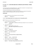
To provision the first alarm scan point, at the RCV terminal type and enter
8.11i
Response:
The REMOTE ALARM ASSIGNMENT page is displayed. The cursor is positioned at the
REMOTE MODULE field.
6.
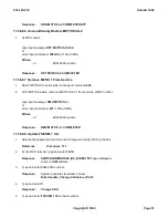
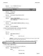
To assign alarms, type and enter data for the following fields:
REMOTE MODULE ____
ALARM POINT _____ (000-054, refer to completed 8.11 form for assignment)
235-105-210
October 1999
Copyright © 1999
Page 8
Summary of Contents for 5ESS-2000
Page 96: ...235 105 210 October 1999 Copyright 1999 Page 2 ...
Page 184: ...235 105 210 October 1999 Copyright 1999 Page 3 ...
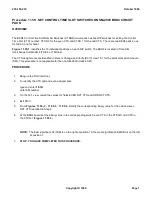
Page 300: ...13 STOP YOU HAVE COMPLETED THIS PROCEDURE 235 105 210 October 1999 Copyright 1999 Page 55 ...
Page 339: ...7 STOP YOU HAVE COMPLETED THIS PROCEDURE 235 105 210 October 1999 Copyright 1999 Page 13 ...
Page 342: ...235 105 210 October 1999 Copyright 1999 Page 2 ...
Page 359: ...235 105 210 October 1999 Copyright 1999 Page 5 ...
Page 609: ...2 STOP YOU HAVE COMPLETED THIS PROCEDURE 235 105 210 October 1999 Copyright 1999 Page 12 ...
Page 676: ...235 105 210 October 1999 Copyright 1999 Page 9 ...
Page 792: ...3 STOP YOU HAVE COMPLETED THIS PROCEDURE 235 105 210 October 1999 Copyright 1999 Page 9 ...
Page 799: ...Figure 11 36 3 1 Cleaning Points 235 105 210 October 1999 Copyright 1999 Page 7 ...
Page 801: ...235 105 210 October 1999 Copyright 1999 Page 9 ...
Page 839: ...2 STOP YOU HAVE COMPLETED THIS PROCEDURE 235 105 210 October 1999 Copyright 1999 Page 16 ...
Page 999: ...2 STOP YOU HAVE COMPLETED THIS PROCEDURE 235 105 210 October 1999 Copyright 1999 Page 13 ...
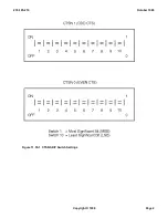
Page 1008: ...Figure 11 55 1 CTSNS DIP Switch Settings 235 105 210 October 1999 Copyright 1999 Page 2 ...
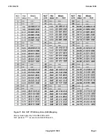
Page 1011: ...235 105 210 October 1999 Copyright 1999 Page 5 ...
Page 1053: ...235 105 210 October 1999 Copyright 1999 Page 15 ...
Page 1289: ...Figure 15 17 2 AMATPS Data Link 235 105 210 October 1999 Copyright 1999 Page 2 ...
Page 1292: ...235 105 210 October 1999 Copyright 1999 Page 5 ...
Page 1303: ...9 STOP YOU HAVE COMPLETED THIS PROCEDURE 235 105 210 October 1999 Copyright 1999 Page 2 ...
Page 1360: ...Figure 15 47 2 Typical SCANS III Link Diagram 235 105 210 October 1999 Copyright 1999 Page 2 ...
Page 1372: ...235 105 210 October 1999 Copyright 1999 Page 2 ...
Page 1374: ...235 105 210 October 1999 Copyright 1999 Page 4 ...
Page 1421: ...Table 1 1 O M Checklist 235 105 210 October 1999 Copyright 1999 Page 3 ...

