Procedure 14.15: CONVERT CI (UN71B) TO CI2 (UN71C) - 5E11 AND LATER
OVERVIEW
This procedure supports the replacement and conversion of the control interface (CI) circuit pack, UN71B, to the
control interface model 2 (CI2) circuit pack, UN71C. The CI2 provides, through peripheral interface control buses
(PICB), communication between the switching module processor (SMP) and peripheral units. The CI2 provides, in
addition to CI functionality, the ability to pump peripheral units in parallel. And, because of its improved scanning
mechanism, it may slightly enhance switching module (SM) performance.
PROCEDURE
14.15.1 PREREQUISITES
1.
Perform this procedure during low traffic periods.
2.
Adhere to Electrostatic Discharge (ESD) protection requirements.
3.
Verify the following documents, applicable to the current system, are available prior to beginning this
procedure.
J5D003L-1
Switching Module Control Cabinet
J5D003AY-1
Single-Shelf Interface Module Processor Unit (SSMPU)
J5D003EC-1
Module Controller and Time Slot Interchange Unit (MCTU)
J5D003LA-1
Module Controller and Time Slot Interchange Unit Model 2
(MCTU2)
J5D003LB-1
Module Controller and Time Slot Interchange Unit Model 3
(MCTU3)
J5D003NA-1
Switch Module Processor Unit Model 4 (SMPU4)
J5D003NG-1
Switch Module Processor Unit Model 5 (SMPU5)
SD5D007-01
5ESS
®
-2000 Switching Equipment Assignment Rules
SD5D012-02
SM Application Schematic
4.
At the master control center (MCC), verify normal conditions in the SM to determine if system status is
acceptable to start the association procedure.
If a NORMAL indication is not obtained, type input message:
OP:SYSSTAT;
5.
Correct deficiencies as required.
14.15.2 PRECONDITIONING
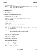
14.15.2.1 Record and Clear Automatic Office Dependent Data Backup
1.
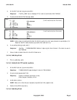
At MCC, type input message:
OP:BKUPSTAT;
Response:
AM CMP=
a
TO
b
NRODD =
c
TO
d
RODD=
c
EVERY=
e
AT=
ff
:
ff
;
or
NG - NO SCHEDULE REQUEST
Where:
a and b; =
range of CMP numbers
c and d; =
range of SM numbers
e; =
Interval in days between scheduled ODD backups
235-105-210
October 1999
Copyright © 1999
Page 1
Summary of Contents for 5ESS-2000
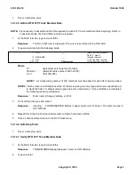
Page 96: ...235 105 210 October 1999 Copyright 1999 Page 2 ...
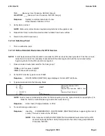
Page 184: ...235 105 210 October 1999 Copyright 1999 Page 3 ...
Page 300: ...13 STOP YOU HAVE COMPLETED THIS PROCEDURE 235 105 210 October 1999 Copyright 1999 Page 55 ...
Page 339: ...7 STOP YOU HAVE COMPLETED THIS PROCEDURE 235 105 210 October 1999 Copyright 1999 Page 13 ...
Page 342: ...235 105 210 October 1999 Copyright 1999 Page 2 ...
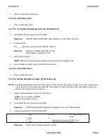
Page 359: ...235 105 210 October 1999 Copyright 1999 Page 5 ...
Page 609: ...2 STOP YOU HAVE COMPLETED THIS PROCEDURE 235 105 210 October 1999 Copyright 1999 Page 12 ...
Page 676: ...235 105 210 October 1999 Copyright 1999 Page 9 ...
Page 792: ...3 STOP YOU HAVE COMPLETED THIS PROCEDURE 235 105 210 October 1999 Copyright 1999 Page 9 ...
Page 799: ...Figure 11 36 3 1 Cleaning Points 235 105 210 October 1999 Copyright 1999 Page 7 ...
Page 801: ...235 105 210 October 1999 Copyright 1999 Page 9 ...
Page 839: ...2 STOP YOU HAVE COMPLETED THIS PROCEDURE 235 105 210 October 1999 Copyright 1999 Page 16 ...
Page 999: ...2 STOP YOU HAVE COMPLETED THIS PROCEDURE 235 105 210 October 1999 Copyright 1999 Page 13 ...
Page 1008: ...Figure 11 55 1 CTSNS DIP Switch Settings 235 105 210 October 1999 Copyright 1999 Page 2 ...
Page 1011: ...235 105 210 October 1999 Copyright 1999 Page 5 ...
Page 1053: ...235 105 210 October 1999 Copyright 1999 Page 15 ...
Page 1289: ...Figure 15 17 2 AMATPS Data Link 235 105 210 October 1999 Copyright 1999 Page 2 ...
Page 1292: ...235 105 210 October 1999 Copyright 1999 Page 5 ...
Page 1303: ...9 STOP YOU HAVE COMPLETED THIS PROCEDURE 235 105 210 October 1999 Copyright 1999 Page 2 ...
Page 1360: ...Figure 15 47 2 Typical SCANS III Link Diagram 235 105 210 October 1999 Copyright 1999 Page 2 ...
Page 1372: ...235 105 210 October 1999 Copyright 1999 Page 2 ...
Page 1374: ...235 105 210 October 1999 Copyright 1999 Page 4 ...
Page 1421: ...Table 1 1 O M Checklist 235 105 210 October 1999 Copyright 1999 Page 3 ...

