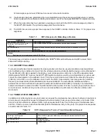
test center transmits MF test priming information to the
5ESS
®
-2000 switch which is interpreted by the ROTL
program. The ROTL program decodes the priming information and connects a TTF or GDSF tone detector to the
trunk under test (TUT) and reserves a TTF responder or GDSF GDG transceiver. If neither of these resources are
available, ROTL will queue them. When the TUT is seized, a 0.5-second burst of test progress tone is sent to
CAROT by ROTL. The FETL number is outpulsed exactly as received in the priming. The far-end office connects to
a 100-type test line. Then, the far-end office transmits a nominal 1004-Hz for a nominal 5.5 seconds to the ROTL
office. This tone is followed by a quiet termination. The tone is detected by ROTL and another 0.5-second burst of
test progress tone is sent from ROTL to CAROT. If prior to the 1004-Hz tone any audible rings or other signals (low
tone) are heard by ROTL, it will send low tone to CAROT that follows the envelope of the received signal. Reorder or
busy tone will appear to be heard directly from the far end by CAROT, but actually the tones have been regenerated.
If the test progress tone is heard instead of the expected milliwatt tone, reorder will be sent to CAROT. The
near-end responder is activated and a third 0.5-second burst of test progress tone is sent to CAROT. This tone is
the signal that CAROT can start making measurements. If the responder in the near-end office is requested by the
test center to make a 1000-Hz loss measurement, the near-end responder measures the received signal from the
trunk under test. The responder then generates a measurement data signal consisting of a 1200-Hz guard tone and
a 2200-Hz data tone followed by a 1200-Hz trailing guard tone. The duration of the data tone is proportional to the
amplitude of the received signal. The measurement data signal is forwarded to the test center. Then, the ROTL
office sends a 1000-Hz signal to the test center for as long as the 1000-Hz signal is present from the far-end office.
The near-end responder resets when the tone is turned off by the far-end office to await additional MF commands
from the test center. The ROTL will continue to wait for measurement commands until one of the following is
received:
CAROT disconnects
Recycle
Release
Release/make-busy.
The maximum elapsed time is 3 minutes.
7.4.2.2 Transmission Tests (102-Type Test Line)
This test is a 1-way loss test (far-to-near) to a 102-type test line in the far-end office. It follows a pattern similar to the
100-type test line. The test center transmits MF test priming information to the
5ESS
®
-2000 switch which is
interpreted by the ROTL program as a request to connect to the trunk under test. The terminating 102-type test line
directory number is then outpulsed to the far-end office over the trunk under test. Unlike the 100 test, no TTF
responder or GDSF GDG transceiver is reserved at this point. When the test line is seized at the far-end office, the
102-type test line transmits 1000
10 Hz at 0 dBm to the ROTL office. When this tone is detected, the second burst
of test progress tone is sent to CAROT as in the 100-type test line call. At this point, ROTL requests a TTF
responder or GDSF GDG transceiver. The third burst of test progress tone is started when the responder is
requested, terminated, available, and ready to make measurements. These types of test lines interrupt the signal
periodically at approximately 10-second intervals. The responder in the ROTL office makes a loss measurement
only when the tone is present so that the interruption in the 1000 Hz from the 102-type test line does not cause any
error in the measurement.
7.4.3 RESPONDER-TO-RESPONDER TESTING
7.4.3.1 Transmission Tests (105-Type Test Line)
7.4.3.1.1 General
235-105-210
October 1999
Copyright © 1999
Page 7
Summary of Contents for 5ESS-2000
Page 96: ...235 105 210 October 1999 Copyright 1999 Page 2 ...
Page 184: ...235 105 210 October 1999 Copyright 1999 Page 3 ...
Page 300: ...13 STOP YOU HAVE COMPLETED THIS PROCEDURE 235 105 210 October 1999 Copyright 1999 Page 55 ...
Page 339: ...7 STOP YOU HAVE COMPLETED THIS PROCEDURE 235 105 210 October 1999 Copyright 1999 Page 13 ...
Page 342: ...235 105 210 October 1999 Copyright 1999 Page 2 ...
Page 359: ...235 105 210 October 1999 Copyright 1999 Page 5 ...
Page 609: ...2 STOP YOU HAVE COMPLETED THIS PROCEDURE 235 105 210 October 1999 Copyright 1999 Page 12 ...
Page 676: ...235 105 210 October 1999 Copyright 1999 Page 9 ...
Page 792: ...3 STOP YOU HAVE COMPLETED THIS PROCEDURE 235 105 210 October 1999 Copyright 1999 Page 9 ...
Page 799: ...Figure 11 36 3 1 Cleaning Points 235 105 210 October 1999 Copyright 1999 Page 7 ...
Page 801: ...235 105 210 October 1999 Copyright 1999 Page 9 ...
Page 839: ...2 STOP YOU HAVE COMPLETED THIS PROCEDURE 235 105 210 October 1999 Copyright 1999 Page 16 ...
Page 999: ...2 STOP YOU HAVE COMPLETED THIS PROCEDURE 235 105 210 October 1999 Copyright 1999 Page 13 ...
Page 1008: ...Figure 11 55 1 CTSNS DIP Switch Settings 235 105 210 October 1999 Copyright 1999 Page 2 ...
Page 1011: ...235 105 210 October 1999 Copyright 1999 Page 5 ...
Page 1053: ...235 105 210 October 1999 Copyright 1999 Page 15 ...
Page 1289: ...Figure 15 17 2 AMATPS Data Link 235 105 210 October 1999 Copyright 1999 Page 2 ...
Page 1292: ...235 105 210 October 1999 Copyright 1999 Page 5 ...
Page 1303: ...9 STOP YOU HAVE COMPLETED THIS PROCEDURE 235 105 210 October 1999 Copyright 1999 Page 2 ...
Page 1360: ...Figure 15 47 2 Typical SCANS III Link Diagram 235 105 210 October 1999 Copyright 1999 Page 2 ...
Page 1372: ...235 105 210 October 1999 Copyright 1999 Page 2 ...
Page 1374: ...235 105 210 October 1999 Copyright 1999 Page 4 ...
Page 1421: ...Table 1 1 O M Checklist 235 105 210 October 1999 Copyright 1999 Page 3 ...


