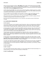
being tested lights.
(C) The yellow Fan Alarm LEDs light on front and rear bezel covers of frame.
(D) The
MAJOR
indicator at the top of the MCC screen lights and the
SM
rectangle
flashes.
(E) At MCC 1010,x page, the
FAN ALM
indicator lights RED and the
SM STAT
status
indicator shows
FAN/FUSE
in reverse video.
(F)
The message
REPT ALM FAN SM=
x [5E9(1) and earlier] or
REPT ALM FAN SM=
x
AISLE=
z [5E9(2) and later] appears on the ROP.
Where:
x = SM number
z = Aisle number
6.
At the MCC, press the
ALM RLS
key.
Response:
(A) Audible MAJOR alarm retires.
(B)
MAJOR
indicator goes OFF.
(C)
SM
indicator stops flashing.
7.
At the SM, insert the fuse removed in Step 5.
8.
At the SM, reseat the Line Group circuit pack [KCD 3 or KCD 3(B)] that was unseated in Step 4.
9.
Restore the Line Group by entering
RST:ISLULGC=a-b-c;
Where:
a = SM number
b = ISLU number
c = Line Group Controller number
Response:
RST ISLULGC=a-b-c COMPLETED
10.
At the SM, test the hardware alarm retire by pressing the red reset button on the rear of the ISLU drawer next
to the fan alarm LEDs.
Response:
(A) Red LED corresponding to fan being tested turns off.
(B) Yellow LEDs extinguish on front and rear bezel covers of frame.
(C) At MCC 1010,x page, the
FAN ALM
indicator returns to normal video and the
SM
STAT
status indicator returns to normal.
(D) The message
REPT ALM CLR FAN SM=
x [5E9(1) and earlier] or
REPT ALM CLR
FAN SM=
x
AISLE=
z [5E9(2) and later] appears on the ROP.
235-105-210
October 1999
Copyright © 1999
Page 2
Summary of Contents for 5ESS-2000
Page 96: ...235 105 210 October 1999 Copyright 1999 Page 2 ...
Page 184: ...235 105 210 October 1999 Copyright 1999 Page 3 ...
Page 300: ...13 STOP YOU HAVE COMPLETED THIS PROCEDURE 235 105 210 October 1999 Copyright 1999 Page 55 ...
Page 339: ...7 STOP YOU HAVE COMPLETED THIS PROCEDURE 235 105 210 October 1999 Copyright 1999 Page 13 ...
Page 342: ...235 105 210 October 1999 Copyright 1999 Page 2 ...
Page 359: ...235 105 210 October 1999 Copyright 1999 Page 5 ...
Page 609: ...2 STOP YOU HAVE COMPLETED THIS PROCEDURE 235 105 210 October 1999 Copyright 1999 Page 12 ...
Page 676: ...235 105 210 October 1999 Copyright 1999 Page 9 ...
Page 792: ...3 STOP YOU HAVE COMPLETED THIS PROCEDURE 235 105 210 October 1999 Copyright 1999 Page 9 ...
Page 799: ...Figure 11 36 3 1 Cleaning Points 235 105 210 October 1999 Copyright 1999 Page 7 ...
Page 801: ...235 105 210 October 1999 Copyright 1999 Page 9 ...
Page 839: ...2 STOP YOU HAVE COMPLETED THIS PROCEDURE 235 105 210 October 1999 Copyright 1999 Page 16 ...
Page 999: ...2 STOP YOU HAVE COMPLETED THIS PROCEDURE 235 105 210 October 1999 Copyright 1999 Page 13 ...
Page 1008: ...Figure 11 55 1 CTSNS DIP Switch Settings 235 105 210 October 1999 Copyright 1999 Page 2 ...
Page 1011: ...235 105 210 October 1999 Copyright 1999 Page 5 ...
Page 1053: ...235 105 210 October 1999 Copyright 1999 Page 15 ...
Page 1289: ...Figure 15 17 2 AMATPS Data Link 235 105 210 October 1999 Copyright 1999 Page 2 ...
Page 1292: ...235 105 210 October 1999 Copyright 1999 Page 5 ...
Page 1303: ...9 STOP YOU HAVE COMPLETED THIS PROCEDURE 235 105 210 October 1999 Copyright 1999 Page 2 ...
Page 1360: ...Figure 15 47 2 Typical SCANS III Link Diagram 235 105 210 October 1999 Copyright 1999 Page 2 ...
Page 1372: ...235 105 210 October 1999 Copyright 1999 Page 2 ...
Page 1374: ...235 105 210 October 1999 Copyright 1999 Page 4 ...
Page 1421: ...Table 1 1 O M Checklist 235 105 210 October 1999 Copyright 1999 Page 3 ...


