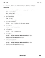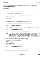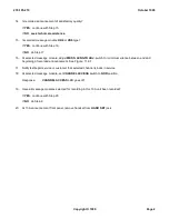
Procedure 11.3: RECORD ANNOUNCEMENTS USING TAPE
13A RECORDED
ANNOUNCEMENT SYSTEM
PROCEDURE
1.
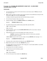
At 13A recorded announcement unit (13A unit) front panel, connect tape recorder to
TAPE
jack with patch
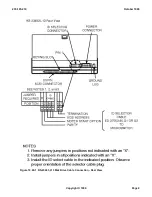
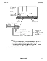
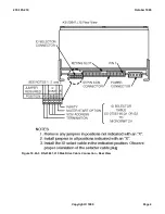
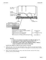
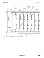
cord. See Figure 11.2-1 .
2.
Note:
Length of recorded announcement must be within the maximum time established per message module
(24 seconds for
UD4
and 12 seconds for
UD5
and
UD6
).
Load tape recorder with appropriate prerecorded announcement tape, as required.
3.
At 13A unit, select message module to be recorded.
4.
At selected message module, set
CHANNEL ACCESS
switch to
ACCESS
position.
Response:
CHANNEL ACCESS
LED lights.
5.
Is selected message module a variable message length (VML) type (UD4 or UD6)?
If
YES
, continue with Step 6.
If
NO
, go to Step 7.
6.
At selected message module, verify that the
MESS LENGTH ADJ.
switch is set to maximum message
length. See Figure 11.2-1 .
7.
Notify test/repair service or customer that selected channel will be out of service.
8.
CAUTION:
Avoid using a handset with tape recorder since this can cause undesirable
background noise to be recorded.
At
UD3
or
UD3B
timing and control circuit pack, depress and release
RECORD
switch. See Figure 11.2-1 .
Response:
Red
REQUEST RECORD
LED lights.
9.
Using tape recorder, start recording immediately when green
RECORD
LED lights.
10.
Note:
Recording period is over when green
RECORD
LED goes out.
At 13A Recorded Announcement front panel, after recording ends, connect handset (G3DR-61 or equivalent)
into
HAND SET
jack. See Figure 11.2-1 .
11.
Using handset, monitor recorded announcement.
12.
Is recorded announcement of satisfactory quality?
If
YES
, go to Step 20.
If
NO
, continue with Step 13.
13.
At 13A unit front panel, remove handset from
HAND SET
jack.
235-105-210
October 1999
Copyright © 1999
Page 1
Summary of Contents for 5ESS-2000
Page 96: ...235 105 210 October 1999 Copyright 1999 Page 2 ...
Page 184: ...235 105 210 October 1999 Copyright 1999 Page 3 ...
Page 300: ...13 STOP YOU HAVE COMPLETED THIS PROCEDURE 235 105 210 October 1999 Copyright 1999 Page 55 ...
Page 339: ...7 STOP YOU HAVE COMPLETED THIS PROCEDURE 235 105 210 October 1999 Copyright 1999 Page 13 ...
Page 342: ...235 105 210 October 1999 Copyright 1999 Page 2 ...
Page 359: ...235 105 210 October 1999 Copyright 1999 Page 5 ...
Page 609: ...2 STOP YOU HAVE COMPLETED THIS PROCEDURE 235 105 210 October 1999 Copyright 1999 Page 12 ...
Page 676: ...235 105 210 October 1999 Copyright 1999 Page 9 ...
Page 792: ...3 STOP YOU HAVE COMPLETED THIS PROCEDURE 235 105 210 October 1999 Copyright 1999 Page 9 ...
Page 799: ...Figure 11 36 3 1 Cleaning Points 235 105 210 October 1999 Copyright 1999 Page 7 ...
Page 801: ...235 105 210 October 1999 Copyright 1999 Page 9 ...
Page 839: ...2 STOP YOU HAVE COMPLETED THIS PROCEDURE 235 105 210 October 1999 Copyright 1999 Page 16 ...
Page 999: ...2 STOP YOU HAVE COMPLETED THIS PROCEDURE 235 105 210 October 1999 Copyright 1999 Page 13 ...
Page 1008: ...Figure 11 55 1 CTSNS DIP Switch Settings 235 105 210 October 1999 Copyright 1999 Page 2 ...
Page 1011: ...235 105 210 October 1999 Copyright 1999 Page 5 ...
Page 1053: ...235 105 210 October 1999 Copyright 1999 Page 15 ...
Page 1289: ...Figure 15 17 2 AMATPS Data Link 235 105 210 October 1999 Copyright 1999 Page 2 ...
Page 1292: ...235 105 210 October 1999 Copyright 1999 Page 5 ...
Page 1303: ...9 STOP YOU HAVE COMPLETED THIS PROCEDURE 235 105 210 October 1999 Copyright 1999 Page 2 ...
Page 1360: ...Figure 15 47 2 Typical SCANS III Link Diagram 235 105 210 October 1999 Copyright 1999 Page 2 ...
Page 1372: ...235 105 210 October 1999 Copyright 1999 Page 2 ...
Page 1374: ...235 105 210 October 1999 Copyright 1999 Page 4 ...
Page 1421: ...Table 1 1 O M Checklist 235 105 210 October 1999 Copyright 1999 Page 3 ...

