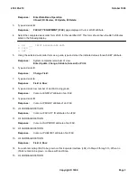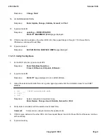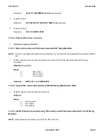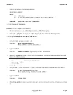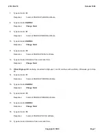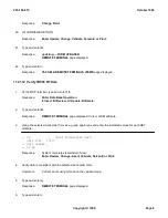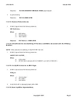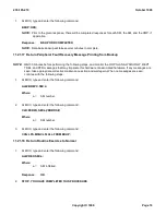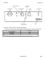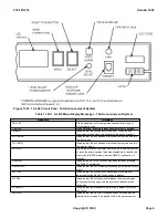
Figure 11.23-1 ALD2 Circuit Pack - 14A Announcement System
Table 11.23-1 ALD2 Menu Display Messages - 14A Announcement System
MESSAGE
COMMENT
ADJ LEV
Allows adjustment of the output transmission level using a 1
kHz reference tone.
CHK SYS
When selected, a complete diagnostic test of ALD2 is made.
IN-SERV
Indicates that the circuit pack is in service. When the unit
receives a ground start, it starts sending the announcement.
LOC MODE
Indicates that the unit has been removed from service and is in
the local mode.
LOC MON
Indicates that the unit has been removed from service and is in
the monitor mode.
PEG CNT
Allows the processor to display from memory the actual number
of times the announcement was broadcasted while the channel
was in the IN-SERV mode, when the SELECT pushbutton is
pressed.
RECORD
Indicates the RECORD function may be selected by pressing
the SELECT pushbutton.
REM MODE
Indicates that the ALD2 is being accessed by the remote record
circuit.
SET LEV
Indicates that the circuit pack's transmission level may be
adjusted after the SELECT pushbutton is pressed.
SIT SEL
Indicates that the SIT (special information tone) preceding an
announcement can be generated internally if desired by the
technician.
STAND BY
Indicates that the processor is performing a diagnostic test on
the circuit.
30S REC
Indicates that the RECORD mode has been selected and the
internal timer is ready to be started to time the announcement
235-105-210
October 1999
Copyright © 1999
Page 4
Summary of Contents for 5ESS-2000
Page 96: ...235 105 210 October 1999 Copyright 1999 Page 2 ...
Page 184: ...235 105 210 October 1999 Copyright 1999 Page 3 ...
Page 300: ...13 STOP YOU HAVE COMPLETED THIS PROCEDURE 235 105 210 October 1999 Copyright 1999 Page 55 ...
Page 339: ...7 STOP YOU HAVE COMPLETED THIS PROCEDURE 235 105 210 October 1999 Copyright 1999 Page 13 ...
Page 342: ...235 105 210 October 1999 Copyright 1999 Page 2 ...
Page 359: ...235 105 210 October 1999 Copyright 1999 Page 5 ...
Page 609: ...2 STOP YOU HAVE COMPLETED THIS PROCEDURE 235 105 210 October 1999 Copyright 1999 Page 12 ...
Page 676: ...235 105 210 October 1999 Copyright 1999 Page 9 ...
Page 792: ...3 STOP YOU HAVE COMPLETED THIS PROCEDURE 235 105 210 October 1999 Copyright 1999 Page 9 ...
Page 799: ...Figure 11 36 3 1 Cleaning Points 235 105 210 October 1999 Copyright 1999 Page 7 ...
Page 801: ...235 105 210 October 1999 Copyright 1999 Page 9 ...
Page 839: ...2 STOP YOU HAVE COMPLETED THIS PROCEDURE 235 105 210 October 1999 Copyright 1999 Page 16 ...
Page 999: ...2 STOP YOU HAVE COMPLETED THIS PROCEDURE 235 105 210 October 1999 Copyright 1999 Page 13 ...
Page 1008: ...Figure 11 55 1 CTSNS DIP Switch Settings 235 105 210 October 1999 Copyright 1999 Page 2 ...
Page 1011: ...235 105 210 October 1999 Copyright 1999 Page 5 ...
Page 1053: ...235 105 210 October 1999 Copyright 1999 Page 15 ...
Page 1289: ...Figure 15 17 2 AMATPS Data Link 235 105 210 October 1999 Copyright 1999 Page 2 ...
Page 1292: ...235 105 210 October 1999 Copyright 1999 Page 5 ...
Page 1303: ...9 STOP YOU HAVE COMPLETED THIS PROCEDURE 235 105 210 October 1999 Copyright 1999 Page 2 ...
Page 1360: ...Figure 15 47 2 Typical SCANS III Link Diagram 235 105 210 October 1999 Copyright 1999 Page 2 ...
Page 1372: ...235 105 210 October 1999 Copyright 1999 Page 2 ...
Page 1374: ...235 105 210 October 1999 Copyright 1999 Page 4 ...
Page 1421: ...Table 1 1 O M Checklist 235 105 210 October 1999 Copyright 1999 Page 3 ...

