2.
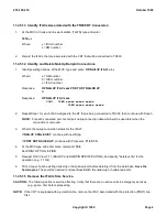
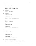
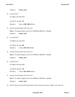
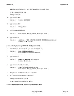
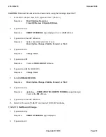
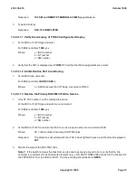
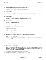
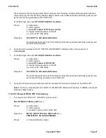
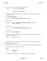
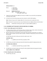
At the MCC type and enter menu command:
196
Reference:
Procedure 11.1
3.
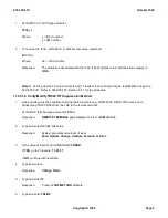
To insert data, type and enter
7.11i
.
Response:
NAIL-UP AND HAIRPIN SPECIFICATION
page is displayed. Cursor at C OE field.
4.
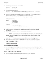
Using the list of existing nail-up or hairpin ports/circuits obtained in Step 11 of Prerequisite Conditions,
perform an insert operation for each nail-up/hairpin circuit that is to be restored.
5.
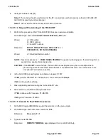
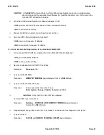
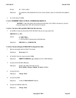
At the MCC to obtain a list of the reestablished nail-ups/hairpin circuits, type and enter:
OP:NAILUP,IFAC=
a-b-c
Where:
a = SM number
b = IDCU number
c = IFAC number.
Response:
OP NAILUP IFAC xxxx
CON1 ILEN xxxxx xxxxx xxxxx
ILEN xxxxx xxxxx xxxxx
6.
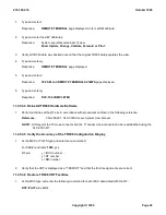
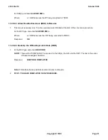
Compare the new list with the previous list to ensure that all the nail-ups/hairpin circuits have been
reestablished.
7.
Reprovision the special service cross-connects in the SLC-2000 database.
NOTE 1:
Reprovisioning must be completed before the cross-connects can be placed into service.
NOTE 2:
Use the CIT to reenter the cross-connect information that was obtained at the start of this
procedure.
Reference:
363-208-003,
SLC-2000 Access System Command and Message Manual
8.
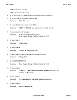
Are lines being moved (rehomed) to the TR303 VRT in conjunction with the conversion procedure?
If
YES
, go to
Procedure
11.45.2
If
NO
, go to Procedure
11.45.4
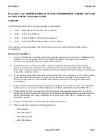
11.45.2 PERFORM LINE REHOMING
1.
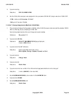
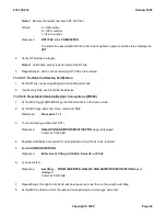
This procedure guides the user through the steps generally associated with relocating lines (rehoming) to a
newly converted VRT. It assumes that all the lines are being relocated from a RT that is being totally
deloaded (vacated). If this is not the case then go to Procedure
11.122.5
, otherwise continue with Procedure
11.45.2.1
.
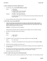
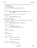
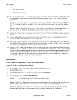
11.45.2.1 Verify Line Size of the TR303 VRT
1.
Is the value of the RT LINE SIZE attribute to be increased (refer to work order form)?
235-105-210
October 1999
Copyright © 1999
Page 18
Summary of Contents for 5ESS-2000
Page 96: ...235 105 210 October 1999 Copyright 1999 Page 2 ...
Page 184: ...235 105 210 October 1999 Copyright 1999 Page 3 ...
Page 300: ...13 STOP YOU HAVE COMPLETED THIS PROCEDURE 235 105 210 October 1999 Copyright 1999 Page 55 ...
Page 339: ...7 STOP YOU HAVE COMPLETED THIS PROCEDURE 235 105 210 October 1999 Copyright 1999 Page 13 ...
Page 342: ...235 105 210 October 1999 Copyright 1999 Page 2 ...
Page 359: ...235 105 210 October 1999 Copyright 1999 Page 5 ...
Page 609: ...2 STOP YOU HAVE COMPLETED THIS PROCEDURE 235 105 210 October 1999 Copyright 1999 Page 12 ...
Page 676: ...235 105 210 October 1999 Copyright 1999 Page 9 ...
Page 792: ...3 STOP YOU HAVE COMPLETED THIS PROCEDURE 235 105 210 October 1999 Copyright 1999 Page 9 ...
Page 799: ...Figure 11 36 3 1 Cleaning Points 235 105 210 October 1999 Copyright 1999 Page 7 ...
Page 801: ...235 105 210 October 1999 Copyright 1999 Page 9 ...
Page 839: ...2 STOP YOU HAVE COMPLETED THIS PROCEDURE 235 105 210 October 1999 Copyright 1999 Page 16 ...
Page 999: ...2 STOP YOU HAVE COMPLETED THIS PROCEDURE 235 105 210 October 1999 Copyright 1999 Page 13 ...
Page 1008: ...Figure 11 55 1 CTSNS DIP Switch Settings 235 105 210 October 1999 Copyright 1999 Page 2 ...
Page 1011: ...235 105 210 October 1999 Copyright 1999 Page 5 ...
Page 1053: ...235 105 210 October 1999 Copyright 1999 Page 15 ...
Page 1289: ...Figure 15 17 2 AMATPS Data Link 235 105 210 October 1999 Copyright 1999 Page 2 ...
Page 1292: ...235 105 210 October 1999 Copyright 1999 Page 5 ...
Page 1303: ...9 STOP YOU HAVE COMPLETED THIS PROCEDURE 235 105 210 October 1999 Copyright 1999 Page 2 ...
Page 1360: ...Figure 15 47 2 Typical SCANS III Link Diagram 235 105 210 October 1999 Copyright 1999 Page 2 ...
Page 1372: ...235 105 210 October 1999 Copyright 1999 Page 2 ...
Page 1374: ...235 105 210 October 1999 Copyright 1999 Page 4 ...
Page 1421: ...Table 1 1 O M Checklist 235 105 210 October 1999 Copyright 1999 Page 3 ...

