1-2
APX 1000™ Getting Started Guide
Overview of APX 1000 System and Features
APX 1000 system overview
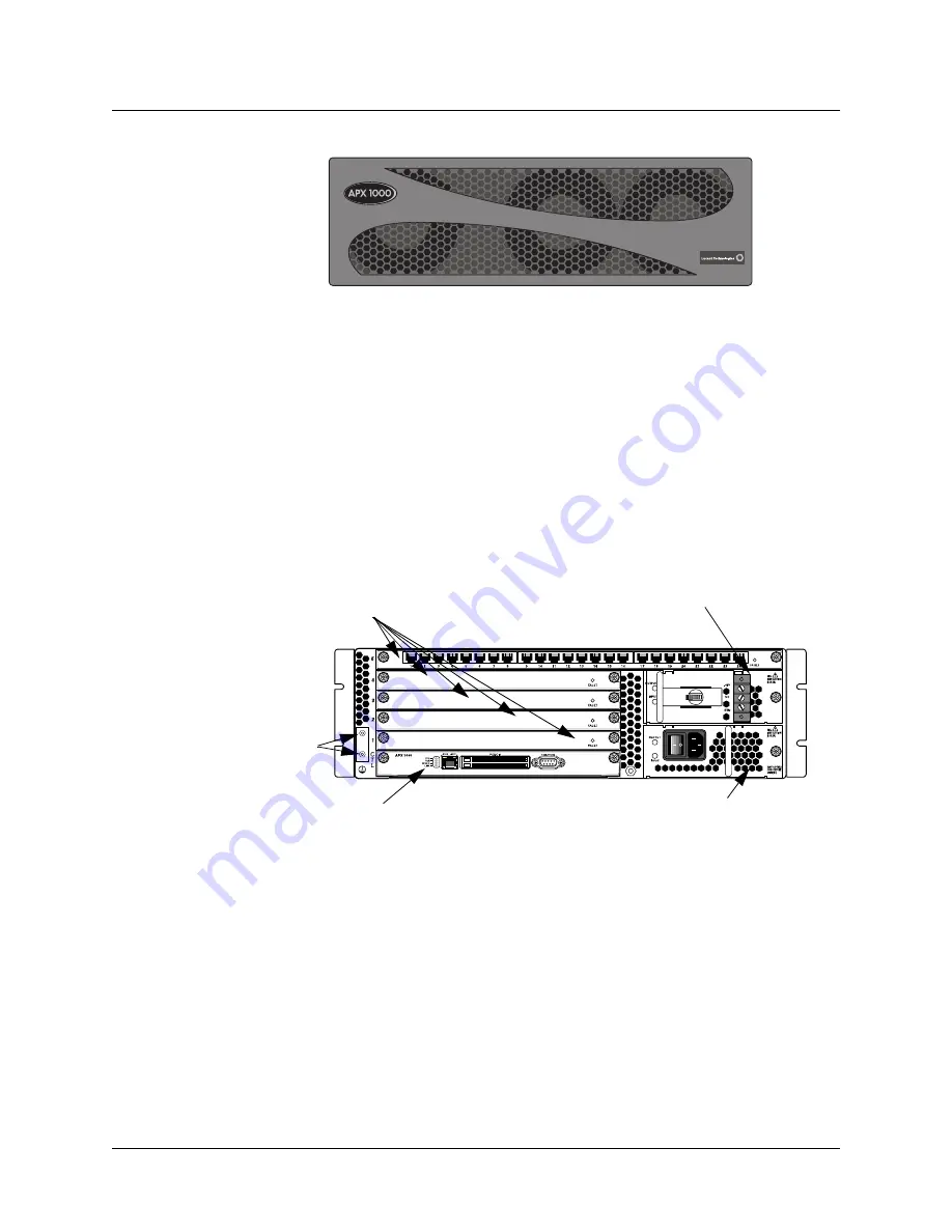
Figure 1-1. APX 1000 chassis, front view
The rear of the APX 1000 chassis, shown in Figure 1-2, consists of the following major
hardware components:
•
One shelf controller
•
Five expansion slots, containing
–
One or two ingress slot cards that support subscriber connections to the APX 1000
–
One egress slot card that passes combined subscriber traffic onto a backbone network
–
Up to three digital signal processor (DSP) slot cards, or two DSP slot cards if a slot is
used for a second E1 ingress card
•
Dual ac or dc power supplies
Slot cards in an APX 1000 unit connect to each other via the backplane. The shelf controller
manages the system and interacts with the slot cards.
Figure 1-2. APX 1000 chassis, rear view
Card slots 1 to 5 (top slot)
Shelf controller
Top power supply
(dc shown)
Bottom power supply
(ac shown)
Ground
terminals


