B-4
APX 1000™ Getting Started Guide
Slot Card Specifications
24-port T1 or E1 slot card
Channelized T3 technical specifications
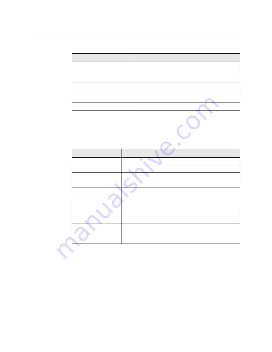
Table B-4 describes the Channelized T3 slot card specifications.
24-port T1 or E1 slot card
The 24-port T1 or E1 slot card (APX1-SL-24CT1CE1), shown in Figure B-4, provides
separate interfaces for 24 individual T1 or E1 lines. The ability of the card to support either T1
or E1 service is determined by application of the appropriate hash code.
Table B-3. T3 slot card status indicators
Status indicator
Meaning when on
LA (Green)
T3 interface is enabled and has not detected any error
conditions.
LF (Yellow)
T3 interface is out of frame alignment.
RA (Red)
T3 interface is experiencing loss of receive signal.
YA (Yellow)
T3 interface has detected Far End Receive Failure indication
transmitted from the other side.
LO (Red)
T3 interface is out of frame alignment.
Table B-4. T3 slot card specifications
Category
Specification
Electrical standards
DSX-3 per ANSI T1.404
Line buildout
0 to 225 feet (0 to 68.58m), or 226 to 450 feet (68.88 to 137.6m)
Receive equalization
Based on cable length and transmitter
Line code
Bipolar 3-zero substitution (B3ZS)
Line rate
44.736Mbps ± 20ppm
Frame format
Per ANSI T1.107a (M23 or C-bit parity)
Alarm signaling
When a DS3 Red alarm occurs, a Yellow alarm is sent on the DS3
line and an AIS is sent on DS2 lines.
On a DS2 Red alarm, an AIS is sent on DS1 lines.
Connectors
Four 75-ohm BNC coaxial (two active lines and two backup
lines)
Operating temperature
32-122° F (0-50° C)


