Beta Draft Confidential
Installing and Removing Modules
Installing or Replacing Power Supplies
6-30
4/5/03
CBX 500 Multiservice WAN Switch Hardware Installation Guide
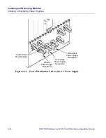
To attach an AC power cord, perform the following steps:
a. Connect the power cord to the primary power supply by plugging the AC
power cord into the Power 1 - IEC 320 inlet on the back of the switch.
Connect the power cord to the secondary power supply by plugging the AC
power cord into the Power 2 - IEC 320 inlet on the back of the switch. For a
redundant power supply, plug the cord into the Power 3 - IEC 320 inlet.
b. Insert the power cord into one or more of the cable strain-relief clamps, and
ensure that there is some slack in the power cord between the clamp and the
IEC 320 inlet.
c.
Verify that the power switch on the power supply is in the STANDBY
position.
d. Plug the power cord into a three-wire grounding receptacle. To ensure
continuous power in the event of an electrical circuit outage, plug the power
cord into a receptacle on a different circuit than the one used by the other
power supplies.
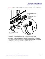
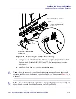
To attach a DC power cord, perform the following steps. Both DC power cords
must be connected at all times when operating the switch.
a. Verify that the power switch on the power supply is set to the STANDBY
position.
b. Locate the three #10 studs on the back of the power supply.
c.
Using a #2 Phillips-head screwdriver, remove the two screws that secure the
protective cover over the studs. Then remove the protective cover.
Note – Before connecting the power cords, see the section,
“Electronic/Electrical
Requirements,”
in Chapter 2. See also
Appendix C
for circuit regulatory information.
Warning – Disconnect the power to the wire leads before you begin this procedure.

