Preparing for the Installation
Verifying the Hardware Configuration
Beta Draft Confidential
3-6
4/5/03
CBX 500 Multiservice WAN Switch Hardware Installation Guide
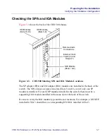
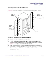
Figure 3-2.
Front View of the CBX 500
Slots 1 and 2 are reserved for the SP modules; they cannot be used for IOP modules.
Slot 1 contains the main SP module and Slot 2 may contain the optional redundant SP
module. If you have a redundant SP configuration, verify that both SPs are the same
model type (both Model 10s; both Model 20s and so on). Also verify that they are the
model type you ordered.
Slots that do not contain IOP modules are masked with blank covers to ensure proper
air flow through the switch.
Grounding Jack
for Wrist Strap
Front
Bezel
Main SP
(Slot 1)
Redundant SP
(Slot 2)
IOP Modules
(Slots 3-9)
IOP Modules
(Slots 10-16)

