Preparing for the Installation
Verifying the Hardware Configuration
Beta Draft Confidential
CBX 500 Multiservice WAN Switch Hardware Installation Guide
4/5/03
3-7
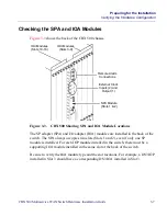
Checking the SPA and IOA Modules
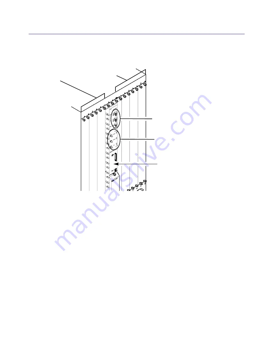
Figure 3-3
shows the back of the CBX 500 chassis.
Figure 3-3.
CBX 500 Showing SPA and IOA Module Locations
The SP adapter (SPA) and I/O adapter (IOA) modules are installed in the back of the
switch. The SPA always occupies two slots (Slots 1 and 2), even if only one SP
module is installed. For each IOP module installed in the switch, there must be a
supporting IOA module installed in the same slot at the back of the switch.
Be sure to verify the IOA module type and the slot locations. For example, a DS3 IOP
installed in Slot 3 should have a corresponding DS3 IOA installed in Slot 3.
SPA Module
(Slots 1 & 2)
Remote Alarm
Connections
External Clock
Inputs (2) and
Output (1)
IOA Modules
(Slots 3-9)
IOA Modules
(Slots 10-16)

