Installing the CBX 500 Switch
Connecting Cables to the Switch
Beta Draft Confidential
CBX 500 Multiservice WAN Switch Hardware Installation Guide
4/5/03
4-9
Connecting Cables to the Switch
After you set up the switch in the desired location, connect the switch to the network
by attaching the appropriate cables to the IOA modules in the back of the switch. The
IOA cables are either coaxial (for OC-3c/STM-1 electrical, DS3, E3, and 75-ohm E1
connections), DB-15 (for T1 and 120-ohm E1 connections), or fiber optic (for
OC-3/STM-1 optical and OC-12c/STM-4 connections).
The SPA module provides the ports for connecting the switch to the NMS or console.
See
Appendix B, “Cables and Pinout Assignments,”
for NMS and console cable
pinouts.
Network Management Connections
The SPA modules support the “network management” connection, which uses a
standard DB-25 port for attaching a console terminal to the switch.
The IOA modules support the “management VC/PVC” connection, which is a
physical port connection on an IOA, not the SPA. This physical connection is viewed
as a “virtual port” that enables the NMS to manage the switch through a single router
or through an ATM network interface card (NIC) UNI-DCE connection.
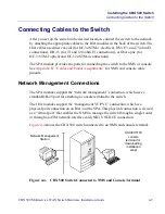
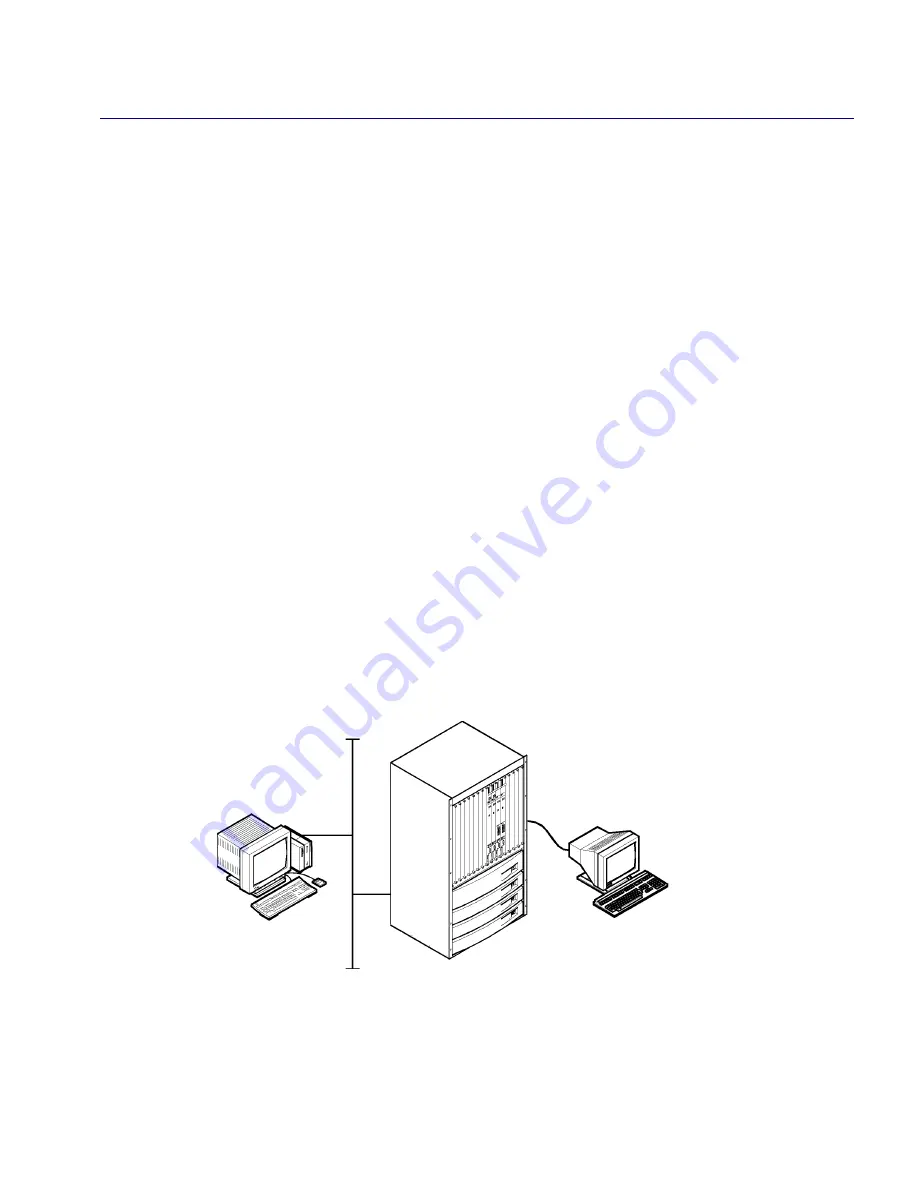
Figure 4-4
shows the CBX 500 switch connected to an NMS and console terminal.
Figure 4-4.
CBX 500 Switch Connected to NMS and Console Terminal
Network Management
Station
ASCII/VT100
console
downloading
terminal for
installation
script


