Determining the Operating Status
Connecting Power to the Switch
Beta Draft Confidential
5-12
4/5/03
CBX 500 Multiservice WAN Switch Hardware Installation Guide
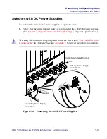
2. Attach a power cord to each set of power connectors as follows. Both power cords
must be connected at all times when operating the switch.
a. Verify that the power switch on the power supply is set to the OFF position.
b. Locate the #10 studs on the back of the unit.
c.
Using a #2 Phillips-head screwdriver, remove the two screws that secure the
protective cover over the studs. Then remove the protective cover.
d. Using a 7/16-in. wrench or socket, remove the top locking nut from each of
the three studs (labelled -48V, RTN, and
). Do not remove the bottom
locking nut.
e.
Install the three ring lugs onto the appropriate posts.
Note – The DC power cord wires should terminate in 1/4-in. diameter listed ring lugs,
using the tools specified by the manufacturer. Also, the wire gauge you use depends
on the distance from the connection point.
Warning – Verify that the power is off or disconnected at the source before beginning
this procedure.
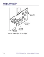
Note – You can optionally ground the chassis to the enclosure by attaching a dual
mount ground lug to the dual mount ground on the back of the unit (see
Figure 5-4 on
page 5-11
).
Note – It is recommended that, to provide a single-point ground connection, only one
of the chassis grounds should be connected to earth ground (
).


