Issue 5 November 2000
363-206-208
Equipment and Front Access Cable Installation for the DDM-2000 OC-12 Multiplexer
Lucent Technologies - Proprietary
See Notice on first page
Planning
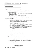
The DDM-2000 OC-12 may be mounted as follows:
a.
Mounted in network bay frame. The recommended network bay frame for front
access is the ED-8C500 or ED-8C800. Refer to Figures 3-4, 3-5, and 3-6 on
Pages 3-49 through Page 3-51 for DDM-2000 OC-12 placement in a network
bay frame.
b.
Miscellaneously mounted, meeting requirements in “Equipment Installation
Considerations”.
Equipment Installation Considerations
Detailed network bay frame installation information is contained in ED-8C727-10,
“Typical Bay Arrangements”. The information in this paragraph is of a general nature.
The equipment listed below has the following height dimensions:
Each DDM-2000 OC-12 shelf installed must have an air gap of at least 3.0 inches
between the bottom of the DDM-2000 OC-12 shelf and the equipment (or bay frame if
the shelf is installed at the bottom of the bay) below it.
A fan shelf and heat baffle are required above each DDM-2000 OC-12 shelf. Refer to
the bay layout shown in Figure 3-5 on page 3-50 and Figure 3-6 on page 3-51.
A heat baffle must be installed below the DDM-2000 OC-12 if any heat generating
equipment is located below the DDM-2000 OC-12.
NOTE:
DDM-2000 OC-12 heat baffles must be used where required. There is no equiv-
alent air gap.
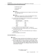
ED-8C727-30, G1
DDM-2000 OC-12 Shelf
14.0 inches
ED-8C733-30, G1
Heat Baffle
4.0 inches
ED-8C733-30, G8
DDM-2000 OC-12 Fan Shelf
4.0 inches
Summary of Contents for DDM-2000 OC-12
Page 4: ......
Page 370: ...GL 22 Issue 5 June 2000 363 206 208 Glossary ...
Page 382: ...363 206 208 Index 1 ...


