Issue 5 November 2000
363-206-208
Equipment and Front Access Cable Installation for the DDM-2000 OC-12 Multiplexer
Lucent Technologies - Proprietary
See Notice on first page
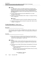
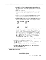
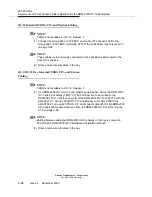
f. When the solder joint is cooled, reconnect the 219A shield and return the
734A cable to its vertical position.
(6) Label the DS3 cables, indicating bay, shelf, muldem (A, B, C, or D), and direc-
tion (IN or OUT of the bay) at each end.
NOTE:
When cabling to a DSX, the DSX becomes an extention of the DDM-2000 back-
plane connections. Thus the IN on the DDM-2000 backplane connects to the IN
of the DSX and the OUT of the DDM-2000 backplane connects to the OUT of the
DSX respectively.
Optical Fiber Cable Installation
Description
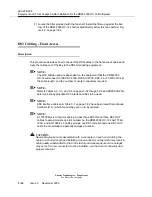
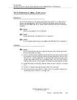
This procedure describes how to connect the fiber optic cables to the shelf and route
the cables out of the bay to the lightguide cable interconnection equipment/module
(LCIE/M) or
LGX
®
optical cross-connection.
This procedure does not cover routing the optical fiber cable between central office
locations.
Procedure
NOTE:
The optical fiber cables for front access and rear access are installed in the same
manner.
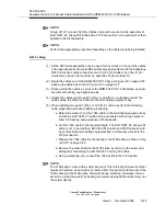
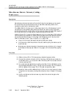
(1) Perform the “Optical Fiber Cable Installation - Rear Access” procedure in the
“Equipment and Rear Access Cable Installation” section. The cables should be
routed out of the bay, stacking the cables as shown in Figure 3-2 on page 3-47.
Power Cable Installation - Front Access
Description
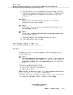
for the power cable installation, follow the “Power Cable Installation - Rear Access” in
the “Equipment and Rear Access Cable Installation” section (see note). The cables
should be routed out of the bay, stacking cables as shown in Figure 3-2 on page 3-47.
Summary of Contents for DDM-2000 OC-12
Page 4: ......
Page 370: ...GL 22 Issue 5 June 2000 363 206 208 Glossary ...
Page 382: ...363 206 208 Index 1 ...

